
Data Sheet


UM10204 All information provided in this document is subject to legal disclaimers. © NXP Semiconductors N.V. 2014. All rights reserved.
User manual Rev. 6 — 4 April 2014 54 of 64
NXP Semiconductors
UM10204
I
2
C-bus specification and user manual
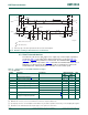
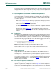
[1] t
VD;DAT
= minimum time for USDA data out to be valid following USCL LOW.
[2] Typical rise time or fall time for UFm signals is 25 ns measured from the 30 % level to the 70 % level (rise time) or from the 70 % level to
the 30 % level (fall time).
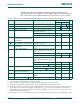
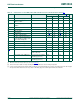
Table 14. UFm I
2
C-bus frequency and timing specifications
Symbol Parameter Conditions Ultra Fast-mode Unit
Min Max
f
USCL
USCL clock frequency 0 5000 kHz
t
BUF
bus free time between a STOP and START condition 80 - ns
t
HD;STA
hold time (repeated) START condition 50 - ns
t
SU;STA
set-up time for a repeated START condition 50 - ns
t
SU;STO
set-up time for STOP condition 50 - ns
t
HD;DAT
data hold time 10 - ns
t
VD;DAT
data valid time
[1]
10 - ns
t
SU;DAT
data set-up time 30 - ns
t
LOW
LOW period of the USCL clock 50 - ns
t
HIGH
HIGH period of the USCL clock 50 - ns
t
f
fall time of both USDA and USCL signals -
[2]
50 ns
t
r
rise time of both USDA and USCL signals -
[2]
50 ns
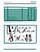
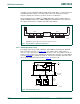
Fig 40. Definition of timing for Ultra Fast-mode devices on the I
2
C-bus
002aag826
t
f
70 %
30 %
USDA
t
f
70 %
30 %
S
t
r
70 %
30 %
70 %
30 %
t
HD;DAT
USCL
1 / f
USCL
1st clock cycle
70 %
30 %
70 %
30 %
t
r
t
VD;DAT
cont.
cont.
USDA
USCL
t
SU;STA
t
HD;STA
Sr
t
SP
t
SU;STO
t
BUF
P S
t
HIGH
9th
clock
t
HD;STA
t
LOW
70 %
30 %
t
VD;ACK
9th
clock
t
SU;DAT