
Data Sheet

UM10204 All information provided in this document is subject to legal disclaimers. © NXP Semiconductors N.V. 2014. All rights reserved.
User manual Rev. 6 — 4 April 2014 44 of 64
NXP Semiconductors
UM10204
I
2
C-bus specification and user manual
5.3.6 Standard, Fast-mode and Fast-mode Plus transfer in a mixed-speed bus
system
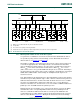
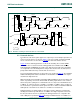
The bridge shown in Figure 36 interconnects corresponding serial bus lines, forming one
serial bus system. As no master code (0000 1XXX) is transmitted, the current-source
pull-up circuits stay disabled and all output stages are open-drain. All devices, including
Hs-mode devices, communicate with each other according to the protocol, format and
speed of the F/S-mode I
2
C-bus specification.
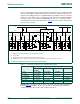
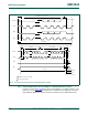
5.3.7 Hs-mode transfer in a mixed-speed bus system
Figure 37 shows the timing diagram of a complete Hs-mode transfer, which is invoked by
a START condition, a master code, and a not-acknowledge A
(at F/S-mode speed).
Although this timing diagram is split in two parts, it should be viewed as one timing
diagram were time point t
H
is a common point for both parts.
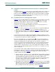
The master code is recognized by the bridge in the active or non-active master (see
Figure 36
). The bridge performs the following actions:
1. Between t
1
and t
H
(see Figure 37), transistor TR1 opens to separate the SDAH and
SDA lines, after which transistor TR3 closes to pull-down the SDA line to V
SS
.
2. When both SCLH and SCL become HIGH (t
H
in Figure 37), transistor TR2 opens to
separate the SCLH and SCL lines. TR2 must be opened before SCLH goes LOW
after Sr.
Hs-mode transfer starts after t
H
with a repeated START condition (Sr). During Hs-mode
transfer, the SCL line stays at a HIGH and the SDA line at a LOW steady-state level, and
so is prepared for the transfer of a STOP condition (P).
After each acknowledge (A) or not-acknowledge bit (A
), the active master disables its
current-source pull-up circuit. This enables other devices to delay the serial transfer by
stretching the LOW period of the SCLH signal. The active master re-enables its
current-source pull-up circuit again when all devices are released and the SCLH signal
reaches a HIGH level, and so speeds up the last part of the SCLH signal rise time. In
irregular situations, F/S-mode devices can close the bridge (TR1 and TR2 closed, TR3
open) at any time by pulling down the SCL line for at least 1 μs, for example, to recover
from a bus hang-up.
Hs-mode finishes with a STOP condition and brings the bus system back into the
F/S-mode. The active master disables its current-source MCS when the STOP condition
(P) at SDAH is detected (t
FS
in Figure 37). The bridge also recognizes this STOP
condition and takes the following actions:
1. Transistor TR2 closes after t
FS
to connect SCLH with SCL; both of which are HIGH at
this time. Transistor TR3 opens after t
FS
, which releases the SDA line and allows it to
be pulled HIGH by the pull-up resistor R
p
. This is the STOP condition for the
F/S-mode devices. TR3 must open fast enough to ensure the bus free time between
the STOP condition and the earliest next START condition is according to the
Fast-mode specification (see t
BUF
in Table 10).
2. When SDA reaches a HIGH (t
2
in Figure 37), transistor TR1 closes to connect SDAH
with SDA. (Note: interconnections are made when all lines are HIGH, thus preventing
spikes on the bus lines.) TR1 and TR2 must be closed within the minimum bus free
time according to the Fast-mode specification (see t
BUF
in Table 10).