
Data Sheet

UM10204 All information provided in this document is subject to legal disclaimers. © NXP Semiconductors N.V. 2014. All rights reserved.
User manual Rev. 6 — 4 April 2014 42 of 64
NXP Semiconductors
UM10204
I
2
C-bus specification and user manual
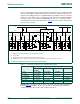
5.3.5 Mixed speed modes on one serial bus system
If a system has a combination of Hs-mode, Fast-mode and/or Standard-mode devices,
it is possible, by using an interconnection bridge, to have different bit rates between
different devices (see Figure 36
and Figure 37).
One bridge is required to connect/disconnect an Hs-mode section to/from an F/S-mode
section at the appropriate time. This bridge includes a level shift function that allows
devices with different supply voltages to be connected. For example F/S-mode devices
with a V
DD2
of 5 V can be connected to Hs-mode devices with a V
DD1
of 3 V or less
(that is, where V
DD2
≥ V
DD1
), provided SDA and SCL pins are 5 V tolerant. This bridge is
incorporated in Hs-mode master devices and is completely controlled by the serial signals
SDAH, SCLH, SDA and SCL. Such a bridge can be implemented in any IC as an
autonomous circuit.
TR1, TR2 and TR3 are N-channel transistors. TR1 and TR2 have a transfer gate function,
and TR3 is an open-drain pull-down stage. If TR1 or TR2 are switched on they transfer a
LOW level in both directions, otherwise when both the drain and source rise to a HIGH
level there is a high-impedance between the drain and source of each switched-on
transistor. In the latter case, the transistors act as a level shifter as SDAH and SCLH are
pulled-up to V
DD1
and SDA and SCL are pulled-up to V
DD2
.
During F/S-mode speed, a bridge on one of the Hs-mode masters connects the SDAH
and SCLH lines to the corresponding SDA and SCL lines thus permitting Hs-mode
devices to communicate with F/S-mode devices at slower speeds. Arbitration and
synchronization are possible during the total F/S-mode transfer between all connected
devices as described in Section 3.1.7
. During Hs-mode transfer, however, the bridge
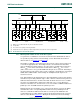
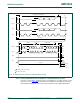
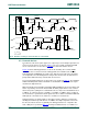
(1) Bridge not used. SDA and SCL may have an alternative function.
(2) To input filter.
(3) The current-source pull-up circuit stays disabled.
(4) Dotted transistors are optional open-drain outputs which can stretch the serial clock signal SCL.
Fig 35. Hs-mode devices at F/S-mode speed
V
SS
V
SS
Hs-mode
SLAVE
SDAH SCLH
V
SS
Hs-mode
MASTER/SLAVE
SDAH SCLH
SDA SCL
R
s
R
s
Hs-mode
SLAVE
SDAH SCLH
V
SS
R
s
R
s
F/S-mode
MASTER/SLAVE
SDA SCL
R
s
R
s
F/S-mode
SLAVE
SDA SCL
V
SS
R
s
R
s
R
s
R
s
V
DD
(1)
(2) (2)
(4) (4) (4)
(2) (2) (2) (2) (2) (2) (2) (2)
(3)
(1)
V
DD
R
p
R
p
SCL
SDA
msc613