
Data Sheet

UM10204 All information provided in this document is subject to legal disclaimers. © NXP Semiconductors N.V. 2014. All rights reserved.
User manual Rev. 6 — 4 April 2014 41 of 64
NXP Semiconductors
UM10204
I
2
C-bus specification and user manual
The non-active, or losing masters:
1. Adapt their SDAH and SCLH input filters according to the spike suppression
requirement in Hs-mode.
2. Wait for a STOP condition to detect when the bus is free again.
All slaves:
1. Adapt their SDAH and SCLH input filters according to the spike suppression
requirement in Hs-mode.
2. Adapt the set-up and hold times according to the Hs-mode requirements. This
requirement may already be fulfilled by the adaptation of the input filters.
3. Adapt the slope control of their SDAH output stages, if necessary. For slave devices,
slope control is applicable for the SDAH output stage only and, depending on circuit
tolerances, both the Fast-mode and Hs-mode requirements may be fulfilled without
switching its internal circuit.
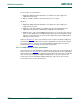
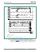
At time t
FS
in Figure 34, each connected device must recognize the STOP condition (P)
and switch its internal circuit from the Hs-mode setting back to the Fast-mode setting as
present before time t
1
. This must be completed within the minimum bus free time as
specified in Table 10
according to the Fast-mode specification.
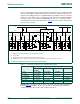
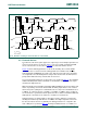
5.3.4 Hs-mode devices at lower speed modes
Hs-mode devices are fully downwards compatible, and can be connected to an F/S-mode
I
2
C-bus system (see Figure 35). As no master code is transmitted in such a configuration,
all Hs-mode master devices stay in F/S-mode and communicate at F/S-mode speeds with
their current-source disabled. The SDAH and SCLH pins are used to connect to the
F/S-mode bus system, allowing the SDA and SCL pins (if present) on the Hs-mode
master device to be used for other functions.