
Data Sheet

UM10204 All information provided in this document is subject to legal disclaimers. © NXP Semiconductors N.V. 2014. All rights reserved.
User manual Rev. 6 — 4 April 2014 38 of 64
NXP Semiconductors
UM10204
I
2
C-bus specification and user manual
proceeded by an acknowledge bit, the rise time of the SCLH clock pulses in Hs-mode
transfers is shortened by the internal current-source pull-up circuit MCS of the active
master.
5.3.2 Serial data format in Hs-mode
Serial data transfer format in Hs-mode meets the Standard-mode I
2
C-bus specification.
Hs-mode can only commence after the following conditions (all of which are in F/S-mode):
1. START condition (S)
2. 8-bit master code (0000 1XXX)
3. Not-acknowledge bit (A
)
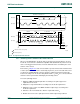
Figure 33
and Figure 34 show this in more detail. This master code has two main
functions:
• It allows arbitration and synchronization between competing masters at F/S-mode
speeds, resulting in one winning master.
• It indicates the beginning of an Hs-mode transfer.
Hs-mode master codes are reserved 8-bit codes, which are not used for slave addressing
or other purposes. Furthermore, as each master has its own unique master code, up to
eight Hs-mode masters can be present on the one I
2
C-bus system (although master code
0000 1000 should be reserved for test and diagnostic purposes). The master code for an
Hs-mode master device is software programmable and is chosen by the System
Designer.
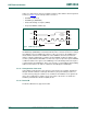
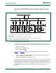
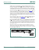
(1) SDA and SCL are not used here but may be used for other functions.
(2) To input filter.
(3) Only the active master can enable its current-source pull-up circuit.
(4) Dotted transistors are optional open-drain outputs which can stretch the serial clock signal SCLH.
Fig 32. I
2
C-bus configuration with Hs-mode devices only
msc612
V
SS
SLAVE
SDAH SCLH
V
SS
MASTER/SLAVE
SDAH SCLH
SDA
MCS
SCL
R
s
R
s
SLAVE
SDAH SCLH
V
SS
R
s
R
s
R
s
R
s
V
DD
V
SS
MASTER/SLAVE
SDAH SCLH
SDA SCL
R
s
R
s
V
DD
(1) (1)(1) (1)
(2) (2)
(4) (4) (3)
MCS
(3)
(2) (2) (2) (2) (2) (2)
V
DD
R
p
R
p
SCLH
SDAH