
Data Sheet

UM10204 All information provided in this document is subject to legal disclaimers. © NXP Semiconductors N.V. 2014. All rights reserved.
User manual Rev. 6 — 4 April 2014 35 of 64
NXP Semiconductors
UM10204
I
2
C-bus specification and user manual
4.5 Advanced Telecom Computing Architecture (ATCA)
Advanced Telecom Computing Architecture (ATCA) is a follow-on to Compact PCI (cPCI),
providing a standardized form-factor with larger card area, larger pitch and larger power
supply for use in advanced rack-mounted telecom hardware. It includes a fault-tolerant
scheme for thermal management that uses I
2
C-bus communications between boards.
Advanced Telecom Computing Architecture (ATCA) is backed by more than
100 companies including many of the large players such as Intel, Lucent, and Motorola.
There are two general compliant approaches to an ATCA-compliant fan control: the first is
an Intelligent FRU (Field Replaceable Unit) which means that the fan control would be
directly connected to the IPMB (Intelligent Platform Management Bus); the second is a
Managed or Non-intelligent FRU.
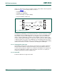
One requirement is the inclusion of hardware and software to manage the dual I
2
C-buses.
This requires an on-board isolated supply to power the circuitry, a buffered dual I
2
C-bus
with rise time accelerators, and 3-state capability. The I
2
C controller must be able to
support a multi-master I
2
C dual bus and handle the standard set of fan commands
outlined in the protocol. In addition, on-board temperature reporting, tray capability
reporting, fan turn-off capabilities, and non-volatile storage are required.
For more information, refer to: www.picmg.org/v2internal/resourcepage2.cfm?id=2
.
4.6 Display Data Channel (DDC)
The Display Data Channel (DDC) allows a monitor or display to inform the host about its
identity and capabilities. The specification for DDC version 2 calls for compliance with the
I
2
C-bus standard mode specification. It allows bidirectional communication between the
display and the host, enabling control of monitor functions such as how images are
displayed and communication with other devices attached to the I
2
C-bus.
For more information, refer to: www.vesa.org
.
5. Bus speeds
Originally, the I
2
C-bus was limited to 100 kbit/s operation. Over time there have been
several additions to the specification so that there are now five operating speed
categories. Standard-mode, Fast-mode (Fm), Fast-mode Plus (Fm+), and High-speed
mode (Hs-mode) devices are downward-compatible — any device may be operated at a
lower bus speed. Ultra Fast-mode devices are not compatible with previous versions
since the bus is unidirectional.
• Bidirectional bus:
– Standard-mode (Sm), with a bit rate up to 100 kbit/s
– Fast-mode (Fm), with a bit rate up to 400 kbit/s
– Fast-mode Plus (Fm+), with a bit rate up to 1 Mbit/s
– High-speed mode (Hs-mode), with a bit rate up to 3.4 Mbit/s.
• Unidirectional bus:
– Ultra Fast-mode (UFm), with a bit rate up to 5 Mbit/s