
Data Sheet

UM10204 All information provided in this document is subject to legal disclaimers. © NXP Semiconductors N.V. 2014. All rights reserved.
User manual Rev. 6 — 4 April 2014 31 of 64
NXP Semiconductors
UM10204
I
2
C-bus specification and user manual
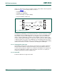
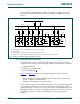
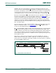
In this case, data transfer can be preceded by a start procedure which is much longer than
normal (see Figure 31
). The start procedure consists of:
• A START condition (S)
• A START byte (0000 0001)
• A Not Acknowledge clock pulse (NACK)
• A repeated START condition (Sr)
After the START condition S has been transmitted by a master which requires bus access,
the START byte (0000 0001) is transmitted. Another microcontroller can therefore sample
the USDA line at a low sampling rate until one of the seven zeros in the START byte is
detected. After detection of this LOW level on the USDA line, the microcontroller can
switch to a higher sampling rate to find the repeated START condition Sr, which is then
used for synchronization. A hardware receiver resets upon receipt of the repeated START
condition Sr and therefore ignores the START byte. An acknowledge-related clock pulse
is generated after the START byte. This is present only to conform with the byte handling
format used on the bus. No device is allowed to acknowledge the START byte.
3.2.13 Unresponsive slave reset
In the unlikely event where the slave becomes unresponsive (for example, determined
through external feedback, not through UFm I
2
C-bus), the preferential procedure is to
reset the slave by using the software reset command or the hardware reset signal. If the
slaves do not support these features, then cycle power to the devices to activate the
mandatory internal Power-On Reset (POR) circuit.
3.2.14 Device ID
The Device ID field is not supported in UFm.
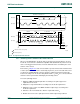
Fig 31. START byte procedure
002aag663
S
9821
Sr
7
NACK
dummy
acknowledge
(HIGH)
START byte 0000 0001
USDA
USCL