
Data Sheet


UM10204 All information provided in this document is subject to legal disclaimers. © NXP Semiconductors N.V. 2014. All rights reserved.
User manual Rev. 6 — 4 April 2014 29 of 64
NXP Semiconductors
UM10204
I
2
C-bus specification and user manual
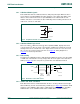
Only the write format previously described for 7-bit addressing is possible with 10-bit
addressing. Detailed here:
• Master-transmitter transmits to slave-receiver with a 10-bit slave address. The
transfer direction is not changed (see Figure 29
). When a 10-bit address follows a
START condition, each slave compares the first seven bits of the first byte of the slave
address (1111 0XX) with its own address and tests if the eighth bit (R/W
direction bit)
is 0 (W
). All slaves that found a match compare the eight bits of the second byte of the
slave address (XXXX XXXX) with their own addresses, but only one slave finds a
match. The matching slave remains addressed by the master until it receives a STOP
condition (P) or a repeated START condition (Sr) followed by a different slave
address.
The START byte 0000 0001 (01h) can precede the 10-bit addressing in the same way as
for 7-bit addressing (see Section 3.2.12
).
3.2.9 Reserved addresses in UFm
The UFm I
2
C-bus has a different physical layer than the other I
2
C-bus modes. Therefore
the available slave address range is different. Two groups of eight addresses (0000 XXX
and 1111 XXX) are reserved for the purposes shown in Table 7
.
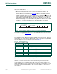
[1] The general call address is used for several functions including software reset.
[2] No UFm device is allowed to acknowledge at the reception of the START byte.
Assignment of addresses within a local system is up to the system architect who must
take into account the devices being used on the bus and any future interaction with
reserved addresses. For example, a device with seven user-assignable address pins
allows all 128 addresses to be assigned. If it is known that the reserved address is never
going to be used for its intended purpose, then a reserved address can be used for a
slave address.
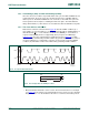
Fig 29. A master-transmitter addresses a slave-receiver with a 10-bit address
002aag661
W
A
(write)
A
A
NA
1 1 1 1 0 X X 0
SLAVE ADDRESS
1st 7 BITS
S DATA PDATA
SLAVE ADDRESS
2nd BYTE
Table 7. Reserved addresses
X = don’t care; 1 = HIGH; 0 = LOW.
Slave address R/W bit Description
0000 000 0 general call address
[1]
0000 000 1 START byte
[2]
0000 001 X reserved for future purposes
0000 010 X reserved for future purposes
0000 011 X reserved for future purposes
0000 1XX X reserved for future purposes
1111 1XX X reserved for future purposes
1111 0XX X 10-bit slave addressing