
Data Sheet


UM10204 All information provided in this document is subject to legal disclaimers. © NXP Semiconductors N.V. 2014. All rights reserved.
User manual Rev. 6 — 4 April 2014 28 of 64
NXP Semiconductors
UM10204
I
2
C-bus specification and user manual
Notes:
1. Individual transaction or repeated START formats addressing multiple slaves in one
transaction can be used. After the START condition and slave address is repeated,
data can be transferred.
2. All decisions on auto-increment or decrement of previously accessed memory
locations, etc., are taken by the designer of the device.
3. Each byte is followed by a Not-Acknowledgment bit as indicated by the A
blocks in the
sequence.
4. I
2
C-bus compatible devices must reset their bus logic on receipt of a START or
repeated START condition such that they all anticipate the sending of a slave
address, even if these START conditions are not positioned according to the proper
format.
5. A START condition immediately followed by a STOP condition (void message) is an
illegal format. Many devices however are designed to operate properly under this
condition.
6. Each device connected to the bus is addressable by a unique address. A simple
master/slave relationship exists, but it is possible to have multiple identical slaves that
can receive and respond simultaneously, for example, in a group broadcast where all
identical devices are configured at the same time, understanding that it is impossible
to determine that each slave is responsive. Refer to individual component data
sheets.
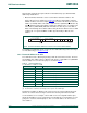
3.2.8 10-bit addressing
10-bit addressing expands the number of possible addresses. Devices with 7-bit and
10-bit addresses can be connected to the same I
2
C-bus, and both 7-bit and 10-bit
addressing can be used in all bus speed modes.
The 10-bit slave address is formed from the first two bytes following a START condition
(S) or a repeated START condition (Sr). The first seven bits of the first byte are the
combination 1111 0XX of which the last two bits (XX) are the two Most Significant Bits
(MSBs) of the 10-bit address; the eighth bit of the first byte is the R/W
bit that determines
the direction of the message.
Although there are eight possible combinations of the reserved address bits 1111 XXX,
only the four combinations 1111 0XX are used for 10-bit addressing. The remaining four
combinations 1111 1XX are reserved for future I
2
C-bus enhancements.
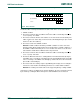
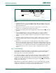
Fig 28. A master-transmitter addressing a slave receiver with a 7-bit address
002aag660
A
‘0’ (write)
data transferred
(n bytes + not acknowledge)
A = not acknowledge (USDA HIGH)
S = START condition
P = STOP condition
W
from master to slave
DATADATAASLAVE ADDRESSS P
A