
Data Sheet


UM10204 All information provided in this document is subject to legal disclaimers. © NXP Semiconductors N.V. 2014. All rights reserved.
User manual Rev. 6 — 4 April 2014 23 of 64
NXP Semiconductors
UM10204
I
2
C-bus specification and user manual
3.2 Ultra Fast-mode I
2
C-bus protocol
The UFm I
2
C-bus is a 2-wire push-pull serial bus that operates from DC to 5 MHz
transmitting data in one direction. It is most useful for speeds greater than 1 MHz to drive
LED controllers and other devices that do not need feedback. The UFm I
2
C-bus protocol
is based on the standard I
2
C-bus protocol that consists of a START, slave address,
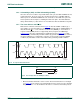
command bit, ninth clock, and a STOP bit. The command bit is a ‘write’ only, and the data
bit on the ninth clock is driven HIGH, ignoring the ACK cycle due to the unidirectional
nature of the bus. The 2-wire push-pull driver consists of a UFm serial clock (USCL) and
serial data (USDA).
Slave devices contain a unique address (whether it is a microcontroller, LCD driver, LED
controller, GPO) and operate only as receivers. An LED driver may be only a receiver and
can be supported by UFm, whereas a memory can both receive and transmit data and is
not supported by UFm.
Since UFm I
2
C-bus uses push-pull drivers, it does not have the multi-master capability of
the wired-AND open-drain Sm, Fm, and Fm+ I
2
C-buses. In UFm, a master is the only
device that initiates a data transfer on the bus and generates the clock signals to permit
that transfer. All other devices addressed are considered slaves.
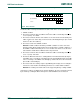
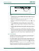
Let us consider the case of a data transfer between a master and multiple slaves
connected to the UFm I
2
C-bus (see Figure 21).
Table 5. Definition of UFm I
2
C-bus terminology
Term Description
Transmitter the device that sends data to the bus
Receiver the device that receives data from the bus
Master the device that initiates a transfer, generates clock signals and
terminates a transfer
Slave the device addressed by a master
Fig 21. Example of UFm I
2
C-bus configuration
002aag654
USDA
USCL
Master ASIC LED
controller 3
LCD
DRIVER
LED
controller 1
LED
controller 2 GPO