
Data Sheet


UM10204 All information provided in this document is subject to legal disclaimers. © NXP Semiconductors N.V. 2014. All rights reserved.
User manual Rev. 6 — 4 April 2014 21 of 64
NXP Semiconductors
UM10204
I
2
C-bus specification and user manual
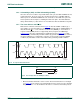
The Device ID is read-only, hard-wired in the device and can be accessed as follows:
1. START condition
2. The master sends the Reserved Device ID I
2
C-bus address followed by the R/W bit
set to ‘0’ (write): ‘1111 1000’.
3. The master sends the I
2
C-bus slave address of the slave device it must identify. The
LSB is a ‘Don’t care’ value. Only one device must acknowledge this byte (the one that
has the I
2
C-bus slave address).
4. The master sends a Re-START condition.
Remark: A STOP condition followed by a START condition resets the slave state
machine and the Device ID Read cannot be performed. Also, a STOP condition or a
Re-START condition followed by an access to another slave device resets the slave
state machine and the Device ID Read cannot be performed.
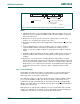
5. The master sends the Reserved Device ID I
2
C-bus address followed by the R/W bit
set to ‘1’ (read): ‘1111 1001’.
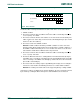
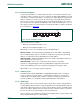
6. The Device ID Read can be done, starting with the 12 manufacturer bits (first byte +
four MSBs of the second byte), followed by the nine part identification bits (four LSBs
of the second byte + five MSBs of the third byte), and then the three die revision bits
(three LSBs of the third byte).
7. The master ends the reading sequence by NACKing the last byte, thus resetting the
slave device state machine and allowing the master to send the STOP condition.
Remark: The reading of the Device ID can be stopped anytime by sending a NACK.
If the master continues to ACK the bytes after the third byte, the slave rolls back to the first
byte and keeps sending the Device ID sequence until a NACK has been detected.
Fig 20. Device ID field
0
002aab942
0 0
00 0 0 0 0 0 0
00 0 0 0 0 0 0
revision
0
0 0 0 0
part identification
manufacturer