
Data Sheet


UM10204 All information provided in this document is subject to legal disclaimers. © NXP Semiconductors N.V. 2014. All rights reserved.
User manual Rev. 6 — 4 April 2014 19 of 64
NXP Semiconductors
UM10204
I
2
C-bus specification and user manual
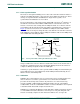
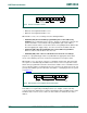
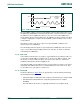
In some systems, an alternative could be that the hardware master transmitter is set in the
slave-receiver mode after the system reset. In this way, a system configuring master can
tell the hardware master-transmitter (which is now in slave-receiver mode) to which
address data must be sent (see Figure 18
). After this programming procedure, the
hardware master remains in the master-transmitter mode.
3.1.14 Software reset
Following a General Call, (0000 0000), sending 0000 0110 (06h) as the second byte
causes a software reset. This feature is optional and not all devices respond to this
command. On receiving this 2-byte sequence, all devices designed to respond to the
general call address reset and take in the programmable part of their address.
Precautions must be taken to ensure that a device is not pulling down the SDA or SCL line
after applying the supply voltage, since these low levels would block the bus.
3.1.15 START byte
Microcontrollers can be connected to the I
2
C-bus in two ways. A microcontroller with an
on-chip hardware I
2
C-bus interface can be programmed to be only interrupted by requests
from the bus. When the device does not have such an interface, it must constantly monitor
the bus via software. Obviously, the more times the microcontroller monitors, or polls the
bus, the less time it can spend carrying out its intended function.
There is therefore a speed difference between fast hardware devices and a relatively slow
microcontroller which relies on software polling.
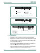
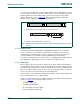
In this case, data transfer can be preceded by a start procedure which is much longer than
normal (see Figure 19
). The start procedure consists of:
• A START condition (S)
• A START byte (0000 0001)
• An acknowledge clock pulse (ACK)
• A repeated START condition (Sr).
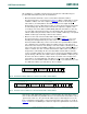
a. Configuring master sends dump address to hardware master
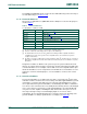
b. Hardware master dumps data to selected slave
Fig 18. Data transfer by a hardware-transmitter capable of dumping data directly to slave
devices
002aac885
write
A
AR/WS PSLAVE ADDR. H/W MASTER DUMP ADDR. FOR H/W MASTER X
002aac886
R/W
write
A
A
(n bytes + ack.)
A/A
S PDUMP ADDR. FROM H/W MASTER DATA DATA