
Data Sheet


UM10204 All information provided in this document is subject to legal disclaimers. © NXP Semiconductors N.V. 2014. All rights reserved.
User manual Rev. 6 — 4 April 2014 17 of 64
NXP Semiconductors
UM10204
I
2
C-bus specification and user manual
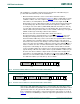
The START byte 0000 0001 (01h) can precede the 10-bit addressing in the same way as
for 7-bit addressing (see Section 3.1.15
).
3.1.12 Reserved addresses
Two groups of eight addresses (0000 XXX and 1111 XXX) are reserved for the purposes
shown in Table 3
.
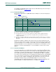
[1] The general call address is used for several functions including software reset.
[2] No device is allowed to acknowledge at the reception of the START byte.
[3] The CBUS address has been reserved to enable the inter-mixing of CBUS compatible and I
2
C-bus
compatible devices in the same system. I
2
C-bus compatible devices are not allowed to respond on
reception of this address.
[4] The address reserved for a different bus format is included to enable I
2
C and other protocols to be mixed.
Only I
2
C-bus compatible devices that can work with such formats and protocols are allowed to respond to
this address.
Assignment of addresses within a local system is up to the system architect who must
take into account the devices being used on the bus and any future interaction with other
conventional I
2
C-buses. For example, a device with seven user-assignable address pins
allows all 128 addresses to be assigned. If it is known that the reserved address is never
going to be used for its intended purpose, a reserved address can be used for a slave
address.
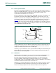
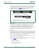
3.1.13 General call address
The general call address is for addressing every device connected to the I
2
C-bus at the
same time. However, if a device does not need any of the data supplied within the general
call structure, it can ignore this address by not issuing an acknowledgment. If a device
does require data from a general call address, it acknowledges this address and behave
as a slave-receiver. The master does not actually know how many devices acknowledged
if one or more devices respond. The second and following bytes are acknowledged by
every slave-receiver capable of handling this data. A slave who cannot process one of
these bytes must ignore it by not-acknowledging. Again, if one or more slaves
acknowledge, the not-acknowledge will not be seen by the master. The meaning of the
general call address is always specified in the second byte (see Figure 16
).
Table 3. Reserved addresses
X = don’t care; 1 = HIGH; 0 = LOW.
Slave address R/W bit Description
0000 000 0 general call address
[1]
0000 000 1 START byte
[2]
0000 001 X CBUS address
[3]
0000 010 X reserved for different bus format
[4]
0000 011 X reserved for future purposes
0000 1XX X Hs-mode master code
1111 1XX 1 device ID
1111 0XX X 10-bit slave addressing