
Data Sheet


UM10204 All information provided in this document is subject to legal disclaimers. © NXP Semiconductors N.V. 2014. All rights reserved.
User manual Rev. 6 — 4 April 2014 15 of 64
NXP Semiconductors
UM10204
I
2
C-bus specification and user manual
3.1.11 10-bit addressing
10-bit addressing expands the number of possible addresses. Devices with 7-bit and
10-bit addresses can be connected to the same I
2
C-bus, and both 7-bit and 10-bit
addressing can be used in all bus speed modes. Currently, 10-bit addressing is not being
widely used.
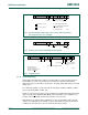
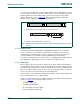
The 10-bit slave address is formed from the first two bytes following a START condition
(S) or a repeated START condition (Sr).
The first seven bits of the first byte are the combination 1111 0XX of which the last two bits
(XX) are the two Most-Significant Bits (MSB) of the 10-bit address; the eighth bit of the
first byte is the R/W
bit that determines the direction of the message.
Although there are eight possible combinations of the reserved address bits 1111 XXX,
only the four combinations 1111 0XX are used for 10-bit addressing. The remaining four
combinations 1111 1XX are reserved for future I
2
C-bus enhancements.
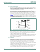
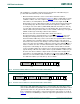
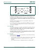
Fig 11. A master-transmitter addressing a slave receiver with a 7-bit address
(the transfer direction is not changed)
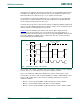
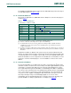
Fig 12. A master reads a slave immediately after the first byte
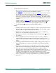
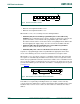
Fig 13. Combined format
mbc605
A/A
A
'0' (write)
data transferred
(n bytes + acknowledge)
A = acknowledge (SDA LOW)
A = not acknowledge (SDA HIGH)
S = START condition
P = STOP condition
R/W
from master to slave
from slave to master
DATADATAASLAVE ADDRESSS P
mbc606
A
(read)
data transferred
(n bytes + acknowledge)
R/W A
1
PDATADATASLAVE ADDRESSSA
mbc607
DATAAR/W
read or write
A/A
DATAAR/W
(n bytes
+ ack.)
*
direction of transfer
may change at this
point.
read or write
(n bytes
+ ack.)
*
Sr = repeated START condition
A/A
*
not shaded because
transfer direction of
data and acknowledge bits
depends on R/W bits.
SLAVE ADDRESSSSrPSLAVE ADDRESS