
Data Sheet


UM10204 All information provided in this document is subject to legal disclaimers. © NXP Semiconductors N.V. 2014. All rights reserved.
User manual Rev. 6 — 4 April 2014 14 of 64
NXP Semiconductors
UM10204
I
2
C-bus specification and user manual
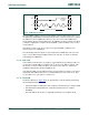
Possible data transfer formats are:
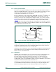
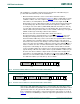
• Master-transmitter transmits to slave-receiver. The transfer direction is not changed
(see Figure 11
). The slave receiver acknowledges each byte.
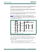
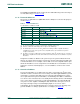
• Master reads slave immediately after first byte (see Figure 12). At the moment of the
first acknowledge, the master-transmitter becomes a master-receiver and the
slave-receiver becomes a slave-transmitter. This first acknowledge is still generated
by the slave. The master generates subsequent acknowledges. The STOP condition
is generated by the master, which sends a not-acknowledge (A
) just before the STOP
condition.
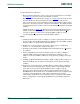
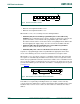
• Combined format (see Figure 13). During a change of direction within a transfer, the
START condition and the slave address are both repeated, but with the R/W
bit
reversed. If a master-receiver sends a repeated START condition, it sends a
not-acknowledge (A
) just before the repeated START condition.
Notes:
1. Combined formats can be used, for example, to control a serial memory. The internal
memory location must be written during the first data byte. After the START condition
and slave address is repeated, data can be transferred.
2. All decisions on auto-increment or decrement of previously accessed memory
locations, etc., are taken by the designer of the device.
3. Each byte is followed by an acknowledgment bit as indicated by the A or A
blocks in
the sequence.
4. I
2
C-bus compatible devices must reset their bus logic on receipt of a START or
repeated START condition such that they all anticipate the sending of a slave
address, even if these START conditions are not positioned according to the proper
format.
5. A START condition immediately followed by a STOP condition (void message) is an
illegal format. Many devices however are designed to operate properly under this
condition.
6. Each device connected to the bus is addressable by a unique address. Normally a
simple master/slave relationship exists, but it is possible to have multiple identical
slaves that can receive and respond simultaneously, for example in a group
broadcast. This technique works best when using bus switching devices like the
PCA9546A where all four channels are on and identical devices are configured at the
same time, understanding that it is impossible to determine that each slave
acknowledges, and then turn on one channel at a time to read back each individual
device’s configuration to confirm the programming. Refer to individual component
data sheets.