
Data Sheet

Multiple VL53L0X application AN4846
4/7 DocID029133 Rev 1
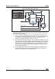
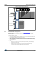
Figure 2. VL53L0X typical application
2. For a board with multiple VL53L0X used in the design, if there are a limited number of
GPIO pins available on the microprocessor, the recommended options for the use of
these GPIO pins available are:
a) If only one GPIO is available from the micro-processor with multiple VL53L0X
devices, then two I2C GPIO expanders would be used, where the first would be
for resetting the devices (XSHUT) and the second would be used for the
interrupts. An example schematic is shown in Figure 3.
b) If (x) VL53L0X devices are being used, and (x+1) GPIOs are available, then it is
recommended to use a GPIO expander for the resetting (XSHUT) of the VL53L0X
devices, and connect each individual interrupt to the microprocessor. Since the
interrupt of each VL53L0X is going directly to the microprocessor, time is saved
when an interrupt is triggered directly to the microprocessor instead of going
through a GPIO expander IC.
c) If (x) VL53L0X devices are being used, and (2x) GPIOs are available, then no
GPIO expander chips are needed, and all reset (XSHUT) and interrupts pins
would be connected directly to the microprocessor.
9//;
5
N
&
)
&
Q)
*3,2,17
6'$
6&/
9''
;6+87
$9''9&6(/
$9669&6(/
*1'
*1'
;6+87
*1'
*1'
$9''
6&/
6'$
'1&
*3,2
9//;
5
N