
Data Sheet


DRV8825
SLVSA73F –APRIL 2010–REVISED JULY 2014
www.ti.com
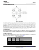
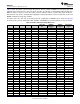
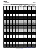
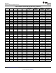
Table 2 shows the relative current and step directions for different settings of MODEx. At each rising edge of the
STEP input, the indexer travels to the next state in the table. The direction is shown with the DIR pin high; if the
DIR pin is low the sequence is reversed. Positive current is defined as xOUT1 = positive with respect to xOUT2.
Note that if the step mode is changed while stepping, the indexer will advance to the next valid state for the new
MODEx setting at the rising edge of STEP.
The home state is 45°. This state is entered at power-up or application of nRESET. This is shown in Table 2 by
the shaded cells. The logic inputs DIR, STEP, nRESET, and MODEx have internal pulldown resistors of 100 kΩ.
Table 2. Relative Current and Step Directions
FULL STEP WINDING WINDING ELECTRICAL
1/32 STEP 1/16 STEP 1/8 STEP 1/4 STEP 1/2 STEP
70% CURRENT A CURRENT B ANGLE
1 1 1 1 1 100% 0% 0
2 100% 5% 3
3 2 100% 10% 6
4 99% 15% 8
5 3 2 98% 20% 11
6 97% 24% 14
7 4 96% 29% 17
8 94% 34% 20
9 5 3 2 92% 38% 23
10 90% 43% 25
11 6 88% 47% 28
12 86% 51% 31
13 7 4 83% 56% 34
14 80% 60% 37
15 8 77% 63% 39
16 74% 67% 42
17 9 5 3 2 1 71% 71% 45
18 67% 74% 48
19 10 63% 77% 51
20 60% 80% 53
21 11 6 56% 83% 56
22 51% 86% 59
23 12 47% 88% 62
24 43% 90% 65
25 13 7 4 38% 92% 68
26 34% 94% 70
27 14 29% 96% 73
28 24% 97% 76
29 15 8 20% 98% 79
30 15% 99% 82
31 16 10% 100% 84
32 5% 100% 87
33 17 9 5 3 0% 100% 90
34 –5% 100% 93
35 18 –10% 100% 96
36 –15% 99% 98
37 19 10 –20% 98% 101
38 –24% 97% 104
39 20 –29% 96% 107
14 Submit Documentation Feedback Copyright © 2010–2014, Texas Instruments Incorporated
Product Folder Links: DRV8825