
Data Sheet


DRV8825
www.ti.com
SLVSA73F –APRIL 2010–REVISED JULY 2014
Feature Description (continued)
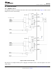
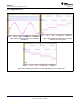
Figure 7. Decay Mode
The DRV8825 supports fast decay, slow decay and a mixed decay mode. Slow, fast, or mixed decay mode is
selected by the state of the DECAY pin; logic low selects slow decay, open selects mixed decay operation, and
logic high sets fast decay mode. The DECAY pin has both an internal pullup resistor of approximately 130 kΩ
and an internal pulldown resistor of approximately 80 kΩ. This sets the mixed decay mode if the pin is left open
or undriven.
Mixed decay mode begins as fast decay, but at a fixed period of time (75% of the PWM cycle) switches to slow
decay mode for the remainder of the fixed PWM period. This occurs only if the current through the winding is
decreasing (per the indexer step table); if the current is increasing, then slow decay is used.
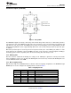
8.3.4 Blanking Time
After the current is enabled in an H-bridge, the voltage on the xISEN pin is ignored for a fixed period of time
before enabling the current sense circuitry. This blanking time is fixed at 3.75 μs. Note that the blanking time also
sets the minimum on time of the PWM.
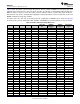
8.3.5 Microstepping Indexer
Built-in indexer logic in the DRV8825 allows a number of different stepping configurations. The MODE0 through
MODE2 pins are used to configure the stepping format as shown in Table 1.
Table 1. Stepping Format
MODE2 MODE1 MODE0 STEP MODE
0 0 0 Full step (2-phase excitation) with 71% current
0 0 1 1/2 step (1-2 phase excitation)
0 1 0 1/4 step (W1-2 phase excitation)
0 1 1 8 microsteps/step
1 0 0 16 microsteps/step
1 0 1 32 microsteps/step
1 1 0 32 microsteps/step
1 1 1 32 microsteps/step
Copyright © 2010–2014, Texas Instruments Incorporated Submit Documentation Feedback 13
Product Folder Links: DRV8825