
Data Sheet

MP6500 – 35V, 2.5A STEP MOTOR DRIVER W/ INTERNAL CURRENT SENSE
MP6500 Rev. 1.0 www.MonolithicPower.com 13
6/22/2017 MPS Proprietary Information. Patent Protected. Unauthorized Photocopy and Duplication Prohibited.
© 2017 MPS. All Rights Reserved.
Blanking Time
There is usually a current spike during the
switching transition due to the body diode’s
reverse-recovery current and the distributed
winding capacitance of the motor. This current
spike requires filtering to prevent it from
erroneously shutting down the HS-FET.
After the PWM cycle begins, the output of the
current sense comparator is ignored for the fixed
blanking time. This blanking time results in a
minimum on time for the PWM cycle.
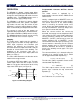
Automatic Decay Mode
The MP6500 uses a fully automatic decay mode
to provide accurate current regulation.
Initially, slow decay is used. At the end of the
fixed off time, if the current is above the I
TRIP
threshold, then fast decay mode is initiated by
reversing the state of the H-bridge outputs.
Once the current level during this fast decay
period drops below the I
TRIP
threshold, slow
decay is again engaged for another fixed off
time. After the completion of this second fixed
off time, a new PWM cycle begins.
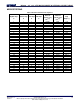
Figure 3 below shows the automatic decay mode
operation during a current reduction as a result
of a step input.
t
OFF
I
OUT
I
TRIP
Slow Decay During t
OFF
Unless
I
OUT
> I
TRIP
at end of t
OFF
t
OFF
t
OFF
t
OFF
t
OFF2
t
OFF
t
OFF
t
OFF
Fast
Decay
I
TRIP
Change
Slow
Decay
Figure 3: Slow Decay During t
OFF
unless I
OUT
>
I
TRIP
at end of t
OFF
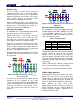
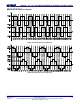
In some cases, specifically high voltage and low
inductance or the regulation of very small
currents, the minimum on time of the PWM cycle
(set by the blanking time described above) can
cause the current to rise very quickly. In this
case, both slow and fast decay are used (see
Figure 4).
t
OFF
I
OUT
I
TRIP
Current regulation of low
current / low inductance
t
OFF
Fast
Decay
t
OFF2
t
OFF
t
OFF2
t
OFF2
Slow
Decay
t
ON_MIN
Figure 4: Current Regulation of Low Current/Low
Inductance
Microstep Selection (MS1, MS2)
The step mode is selected by applying logic high
and low voltages to the MS1 and MS2 (see Table
1). The MP6500 supports full-, half-, quarter-,
and eighth-step modes for progressively finer
step resolution and control.
Table 1: Stepping Format
MS2
MS1
STEP Mode
L
L
Full step
L
H
Half step
H
L
Quarter step
H
H
Eighth step
Full-step mode has four states with each motor
winding driven with either 70.7% of the maximum
positive current or 70.7% of the maximum
negative current. This provides four steps per
electrical rotation. Half-step mode creates eight
steps per electrical rotation. Quarter- and eighth-
step modes provide 16 and 32 steps per rotation
respectively.
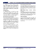
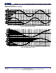
Table 2 and Figure 5 show the relative current
level sequence for different settings of MSx.
The MSx pins have internal pull-down resistors.
SLEEP, nENBL Operation
Driving nSLEEP low puts the device into a low-
power sleep state. In this state, the gate drive
charge pump is stopped, and all the internal
circuits and H-bridge outputs are disabled. All
inputs are ignored when nSLEEP is active low.
When waking up from sleep mode,
approximately 1ms of time must pass before a
STEP command can be issued to allow the
internal circuitry to stabilize. nSLEEP has an
internal pull-down resistor.