
Data Sheet

MP6500 – 35V, 2.5A, STEP MOTOR DRIVER W/ INTERNAL CURRENT SENSE
MP6500 Rev. 1.0 www.MonolithicPower.com 12
6/22/2017 MPS Proprietary Information. Patent Protected. Unauthorized Photocopy and Duplication Prohibited.
© 2017 MPS. All Rights Reserved.
OPERATION
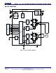
The MP6500 is a bipolar, stepper motor driver
that integrates eight N-channel power MOSFETs
arranged as two full-bridges with 2.5A of current
capability each. The MP6500 operates over a
wide 4.5V to 35V supply voltage range.
The MP6500 is designed to operate bipolar
stepper motors in full-, half-, quarter-, and eighth-
step modes. At each step, the current of each
full-bridge is set by the output voltage of a DAC,
which is controlled by the output of the translator.
The currents in each of the two outputs are
regulated with programmable, constant off-time,
pulse-width modulation (PWM) control circuitry.
The MP6500 integrates internal current sensing
with no external sense resistors required.
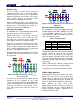
Stepping
The motor moves step-by-step by applying a
series of pulses to STEP. A rising edge on the
STEP input sequences the translator and
advances the motor by one increment. The
translator controls the input to the DACs and the
direction of current flow in each winding. The
amplitude of the increment (step size) is
determined by the state of the inputs (MS1 and
MS2) (see Table 1).
The state of DIR determines the direction of the
rotation of the stepper motor.
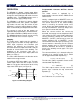
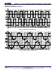
The minimum STEP pulse width is 1µs. The logic
control inputs MSx and DIR require at least
200ns of set-up time and hold time to the rising
edge of the STEP input (see Figure 2).
Step
MSx, DIR
t
A
t
B
t
C
t
D
Figure 2: STEP Timing Diagram
Programmable Constant Off-Time Current
Control
The motor current is regulated by a
programmable constant off-time PWM current
control circuit.
Initially, a diagonal pair of MOSFETs turns on
and drives current through the motor winding.
The current increases in the motor winding,
which is sensed by an internal current sense
circuit. During the initial blanking time (t
BLANK
),
the high-side MOSFET (HS-FET) always turns
on in spite of current limit detection.
When the current reaches the current trip
threshold, the internal current comparator either
shuts off the HS-FET so the winding inductance
current freewheels through the two low-side
MOSFETs (LS-FET) (slow decay) or turns on
another diagonal pair of MOSFETs so the
current flows back to the input (fast decay). The
current continues decreasing for the constant
off-time duration unless a zero current level is
detected. Afterward, the HS-FET is enabled to
increase the winding current again. The cycle
then repeats.
The constant off-time (t
off
) is determined by the
selection of an external resistor (R
OSC
), which
can be approximated with Equation (1):
OFF OSC
t (ns) 115 R (k )
(1)
The full-scale (100%) regulation current can be
calculated with Equation (2):
Max ISET
I 78k /R
(2)
The DAC output reduces the trip current in
precise steps. Calculate the trip current with
Equation (3):
Trip Trip Max
I %I I
(3)
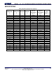
See Table 2 for %I
Trip
at each step.