
Data Sheet

DRV8834
SLVSB19D –FEBRUARY 2012–REVISED MARCH 2015
www.ti.com
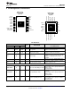
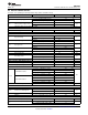
Pin Functions (continued)
PIN
EXTERNAL COMPONENTS
I/O DESCRIPTION
OR CONNECTIONS
NAME HTSSOP VQFN
Indexer mode: Controls microstep mode (full,
half, up to 1/32-step) along with M1.
M0/APHASE 13 10 I Microstep mode/Bridge A phase Phase/enable mode: Logic high sets AOUT1
high, AOUT2 low.
Internal pulldown.
Indexer mode: Controls microstep mode (full,
half, up to 1/32-step) along with M0.
M1 14 11 I Microstep mode/Disable state Phase/enable mode: Determines the state of
the outputs when xENBL = 0.
Internal pulldown.
Logic high to put the device in indexer mode.
Logic low to put the device into phase/enable
CONFIG 15 12 I Device configuration
mode. State is latched at power up and sleep
exit. Internal pulldown.
Logic high to enable device, logic low to enter
nSLEEP 1 22 I Sleep mode input low-power sleep mode and reset all internal
logic.
Reference voltage for AOUT winding current.
In Indexer Mode, it should be tied to a
AVREF 22 19 I Bridge A current set reference input reference voltage for the internal DAC (for
example, VREFO). In Phase/Enable Mode, an
external DAC can drive it for microstepping.
Reference voltage for BOUT winding current.
In Indexer Mode, it should be tied to a
BVREF 23 20 I Bridge B current set reference input reference voltage for the internal DAC (for
example, VREFO). In Phase/Enable Mode, an
external DAC can drive it for microstepping.
Determines decay mode for H-Bridge A (or A
ADECAY 3 24 I Decay mode for bridge A and B in indexer mode) – slow, fast or mixed
decay
Determines decay mode for H-Bridge B –
BDECAY 2 23 I Decay mode for bridge B
slow, fast or mixed decay
STATUS
Logic low when in fault condition (overtemp,
nFAULT 16 13 OD Fault output
overcurrent, undervoltage)
OUTPUT
Connect to current sense resistor for bridge A,
AISEN 5 2 IO Bridge A ground/Isense
or GND if current control not needed
Connect to current sense resistor for bridge B,
BISEN 8 5 IO Bridge B ground/Isense
or GND if current control not needed
AOUT1 4 1 O Bridge A output 1
Connect to motor winding A
AOUT2 6 3 O Bridge A output 2
BOUT1 9 6 O Bridge B output 1
Connect to motor winding B
BOUT2 7 4 O Bridge B output 2
4 Submit Documentation Feedback Copyright © 2012–2015, Texas Instruments Incorporated
Product Folder Links: DRV8834