
Data Sheet


VM
VCP
AOUT1
AOUT2
BOUT1
BOUT2
NFAULT
VINT
AISEN
BISEN
GND
NENBL/AENBL
STEP/BENBL
DIR/BPHASE
M0/APHASE
M1
CONFIG
VREFO
AVREF
BVREF
ADECAY
NSLEEP
BDECAY
VM
Coil A Enable
Coil B Enable
Coil B Direction
Coil A Direction
LOW = SLEEP
VM
10 uf
0.01 uf
2.2 uf
VINT
51K 51K
Stepper
Coil A VREF
Coil B VREF
Coil A Decay
Coil B Decay
Low = Slow
Open = Mixed
High = Fast
DRV8834
www.ti.com
SLVSB19D –FEBRUARY 2012–REVISED MARCH 2015
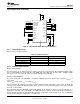
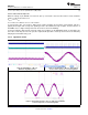
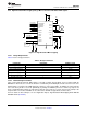
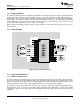
9.2.4 High-Resolution Microstepping Using a Microcontroller to Modulate VREF Signals
Figure 19. High-Resolution Microstepping
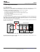
9.2.4.1 Design Requirements
Table 8 lists the design parameters.
Table 8. Design Parameters
PARAMETER REFERENCE EXAMPLE VALUE
Supply voltage V
M
6 V
Motor winding resistance R
L
3.9 Ω
Motor winding inductance I
L
2.9 mH
Motor full step angle θ
step
1.8°/step
Target microstepping level n
m
128 µsteps per step
Target motor speed V 120 RPM
Target full-scale current I
FS
1.25 A
9.2.4.2 Detailed Design Procedure
Using a microcontroller with two DAC outputs, very high resolution microstepping can be performed with the
DRV8834. In this mode, the coil current direction is controlled by the PHASE pins, and the current in each coil is
independently set using the two VREF input pins, which are connected to DACs. In addition, the microcontroller
can set the decay mode for each coil dynamically, by driving the xDECAY pin low for slow decay, high for fast
decay, or high-impedance which sets mixed decay (based on the value of a resistor connected to ground). If the
sleep function is not needed, nSLEEP can be connected to VM with an approximate 47-kΩ resistor.
For more details on this technique, refer to TI Application Report, High Resolution Microstepping Driver With the
DRV88xx Series (SLVA416).
Copyright © 2012–2015, Texas Instruments Incorporated Submit Documentation Feedback 27
Product Folder Links: DRV8834