
Data Sheet
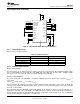


A Current
B Current
1 Step
STEP
DIR
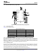
STEP
DIR
A Current
B Current
1 Step
DRV8834
SLVSB19D –FEBRUARY 2012–REVISED MARCH 2015
www.ti.com
9.2.3.2.1 Stepper Motor Speed
The first step in configuring the DRV8834 requires the desired motor speed and microstepping level. If the target
application requires a constant speed, then a square wave with frequency ƒ
step
must be applied to the STEP pin.
If the target motor start-up speed is too high, the motor will not spin. Make sure that the motor can support the
target speed or implement an acceleration profile to bring the motor up to speed.
For a desired motor speed (v), microstepping level (nm), and motor full step angle (θ
step
),
θstep can be found in the stepper motor data sheet or written on the motor itself.
For the DRV8834, the microstepping level is set by the MODE pins and can be any of the settings in Table 6.
Higher microstepping will mean a smoother motor motion and less audible noise, but will increase switching
losses and require a higher f
step
to achieve the same motor speed.
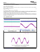
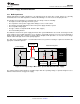
9.2.3.2.2 Current Regulation
In a stepper motor, the set full-scale current (I
FS
) is the maximum current driven through either winding. This
quantity will depend on the xVREF analog voltage and the sense resistor value (R
SENSE
). During stepping, I
FS
defines the current chopping threshold (I
TRIP
) for the maximum current step. The gain of DRV8834 is set for 5
V/V.
To achieve I
FS
= 1.25 A with R
SENSE
of 0.2 Ω, xVREF should be 1.25 V.
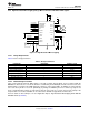
9.2.3.2.3 Decay Modes
The DRV8834 supports three different decay modes: slow decay, fast decay, and mixed decay. The current
through the motor windings is regulated using a fixed-frequency PWM scheme. This means that after any drive
phase, when a motor winding current has hit the current chopping threshold (I
TRIP
), the DRV8834 will place the
winding in one of the three decay modes until the PWM cycle has expired. Afterward, a new drive phase starts.
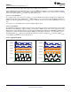
The blanking time T
BLANK
defines the minimum drive time for the current chopping. I
TRIP
is ignored during T
BLANK
,
so the winding current may overshoot the trip level.
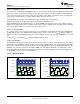
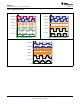
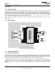
9.2.3.3 Application Curves
Figure 17. Full Step Sequence (2-Phase)
Figure 18. Half Step Sequence (1-2 Phase)
26 Submit Documentation Feedback Copyright © 2012–2015, Texas Instruments Incorporated
Product Folder Links: DRV8834