
Data Sheet


DRV8834
SLVSB19D –FEBRUARY 2012–REVISED MARCH 2015
www.ti.com
T
J
= T
A
+ (P
D
× R
θJA
) = 35°C + (0.64 W x 47° C/W) = 65°C. (3)
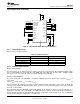
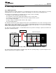
9.2.1.2.3 Motor Current Trip Point
When the voltage on pin SENSE exceeds V
TRIP
(0.5 V), overcurrent is detected. The R
SENSE
resistor should be
sized to set the desired I
TRIP
level.
R
SENSE
= 0.5 V / I
TRIP
(4)
To set I
TRIP
to 2 A, R
SENSE
= 0.5 V / 2 A = 0.25 Ω.
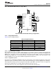
To prevent false trips, I
TRIP
must be higher than regular operating current. Motor current during start-up is
typically much higher than steady-state spinning, because the initial load torque is higher, and the absence of
back-EMF causes a higher voltage and extra current across the motor windings.
It can be beneficial to limit start-up current by using series inductors on the DRV8834 output, as that allows I
TRIP
to be lower, and it may decrease the system’s required bulk capacitance. Start-up current can also be limited by
ramping the forward drive duty cycle.
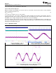
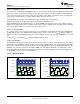
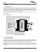
9.2.1.3 Application Curves
Figure 10. Brushed Motor – VM = 8 V, Figure 11. Internal Indexer – VM = 8 V, 1200 Steps per
DRV8834 is Regulating Current second, 1/8 microstep mode, 1-A Current regulation
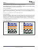
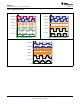
Figure 12. External Microstepping – VM = 8 V, 4000 Steps Per Second,
1/128 microstep mode, 1.2-A Current Regulation
22 Submit Documentation Feedback Copyright © 2012–2015, Texas Instruments Incorporated
Product Folder Links: DRV8834