
Data Sheet

DRV8834
SLVSB19D –FEBRUARY 2012–REVISED MARCH 2015
www.ti.com
When exiting sleep mode, the nFAULT pin will be briefly driven active low as the internal power supplies turn on.
nFAULT will return to inactive high once the internal power supplies (including charge pump) have stabilized.
This process takes some time (up to 1 ms), before the motor driver becomes fully operational.
9 Application and Implementation
NOTE
Information in the following applications sections is not part of the TI component
specification, and TI does not warrant its accuracy or completeness. TI’s customers are
responsible for determining suitability of components for their purposes. Customers should
validate and test their design implementation to confirm system functionality.
9.1 Application Information
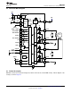
The DRV8834 is a very flexible motor driver. It can be used to drive two DC motors or a stepper motor, in a
number of different configurations.
The following applications schematics show various configurations and connections for the DRV8834.
Component values, especially for RSENSE and the DECAY pins, may be different depending on your motor and
application. Refer to the information above to determine the best values for these components in your
application.
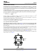
9.1.1 Sense Resistor
For optimal performance, it is important for the sense resistor to be:
• Surface-mount
• Low inductance
• Rated for high enough power
• Placed closely to the motor driver
The power dissipated by the sense resistor equals I
RMS
2
× R. For example, if peak motor current is 3 A, RMS
motor current is 2 A, and a 0.05-Ω sense resistor is used, the resistor will dissipate 2
A
2
× 0.05 Ω = 0.2 W. The
power quickly increases with higher current levels.
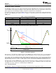
Resistors typically have a rated power within some ambient temperature range, along with a derated power curve
for high ambient temperatures. When a PCB is shared with other components generating heat, margin should be
added. It is always best to measure the actual sense resistor temperature in a final system, along with the power
MOSFETs, as those are often the hottest components.
Because power resistors are larger and more expensive than standard resistors, it is common practice to use
multiple standard resistors in parallel, between the sense node and ground. This distributes the current and heat
dissipation.
9.2 Typical Application
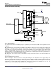
9.2.1 Phase/Enable Mode Driving Two DC Motors
In this configuration, the DRV8834 is used to drive two independent DC motors. Current up to 1 A per motor is
possible. The M1 pin is pulled low to allow slow decay PWM from the controller (if desired) to control the motor
speed by PWMing the xENBL inputs, and ADECAY and BDECAY are connected to ground to set slow decay
mode during current limiting. The value of the RSENSE resistors shown is for a 1-A current limit; if current
limiting is not needed, the AISEN and BISEN pins may be connected directly to ground. If the sleep function is
not needed, nSLEEP can be connected to VM with an approximate 47-kΩ resistor.
20 Submit Documentation Feedback Copyright © 2012–2015, Texas Instruments Incorporated
Product Folder Links: DRV8834