
Data Sheet

DRV8834
www.ti.com
SLVSB19D –FEBRUARY 2012–REVISED MARCH 2015
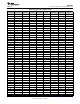
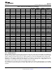
Table 4. Current and Step Directions (continued)
FULL STEP WINDING WINDING ELECTRICAL
1/32 STEP 1/16 STEP 1/8 STEP 1/4 STEP 1/2 STEP
70% CURRENT A CURRENT B ANGLE
95 48 –10% –100% 264
96 –5% –100% 267
97 49 25 13 7 0% –100% 270
98 5% –100% 273
99 50 10% –100% 276
100 15% –99% 278
101 51 26 20% –98% 281
102 24% –97% 284
103 52 29% –96% 287
104 34% –94% 290
105 53 27 14 38% –92% 293
106 43% –90% 295
107 54 47% –88% 298
108 51% –86% 301
109 55 28 56% –83% 304
110 60% –80% 307
111 56 63% –77% 309
112 67% –74% 312
113 57 29 15 8 4 71% –71% 315
114 74% –67% 318
115 58 77% –63% 321
116 80% –60% 323
117 59 30 83% –56% 326
118 86% –51% 329
119 60 88% –47% 332
120 90% –43% 335
121 61 31 16 92% –38% 338
122 94% –34% 340
123 62 96% –29% 343
124 97% –24% 346
125 63 32 98% –20% 349
126 99% –15% 352
127 64 100% –10% 354
128 100% –5% 357
8.4.3 nSLEEP Operation
Driving nSLEEP low will put the device into a low-power sleep state. In this state, the H-bridges are disabled, the
gate drive charge pump is stopped, all internal logic is reset (this returns the indexer to the home state), the VINT
supply is disabled, and all internal clocks are stopped. All inputs are ignored until nSLEEP returns inactive high.
Because the VINT supply is disabled during sleep mode, it cannot be used to provide a logic high signal to the
nSLEEP pin. To simplify board design, the nSLEEP can be pulled up directly to the supply (VM) if it is not
actively driven. Unless VM is less than 5.75 V, a pullup resistor is required.
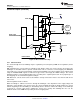
The nSLEEP pin is protected by a Zener diode that will clamp the pin voltage to approximately 6.5 V. The pullup
resistor limits the current to the input in case VM is higher than 6.5 V. The recommended pullup resistor is 20 kΩ
to 50 kΩ.
Copyright © 2012–2015, Texas Instruments Incorporated Submit Documentation Feedback 19
Product Folder Links: DRV8834