
Data Sheet

DRV8834
SLVSB19D –FEBRUARY 2012–REVISED MARCH 2015
www.ti.com
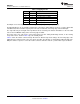
Table 3. Stepping Format
M1 M0 STEP MODE
0 0 Full step (2-phase excitation)
0 1 1/2 step (1-2 phase excitation)
0 Z 1/4 step (W1-2 phase excitation)
1 0 8 microsteps/step
1 1 16 microsteps/step
1 Z 32 microsteps/step
The M0 pin is a tri-level input. It can be driven logic low, logic high, or high-impedance (Z).
The M0 and M1 pins can be statically configured by connecting to VINT, GND, or left open, or can be driven with
standard tristate microcontroller I/O port pins. Their state is latched at each rising edge of the STEP input.
The step mode may be changed on-the-fly while the motor is moving. The indexer will advance to the next valid
state for the new M0/M1 setting at the next rising edge of STEP.
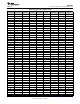
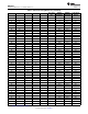
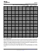
The home state is 45°. This state is entered after power up, after exiting undervoltage lockout, or after exiting
sleep mode. This is shown in Table 4 by cells shaded yellow.
Table 4 shows the relative current and step directions for different step mode settings. At each rising edge of the
STEP input, the indexer travels to the next state in the table. The direction is shown with the DIR pin high; if the
DIR pin is low the sequence is reversed. Positive current is defined as xOUT1 = positive with respect to xOUT2.
16 Submit Documentation Feedback Copyright © 2012–2015, Texas Instruments Incorporated
Product Folder Links: DRV8834