
Data Sheet

DRV8834
www.ti.com
SLVSB19D –FEBRUARY 2012–REVISED MARCH 2015
8.3.3.1 Overcurrent Protection (OCP)
An analog current limit circuit on each FET limits the current through the FET by limiting the gate drive. If this
analog current limit persists for longer than the OCP deglitch time (t
OCP
), all FETs in the H-bridge are disabled
and the nFAULT pin are driven low. The driver will be re-enabled after the OCP retry period (approximately 1.2
ms) has passed. nFAULT becomes high again at this time. If the fault condition is still present, the cycle repeats.
If the fault is no longer present, normal operation resumes and nFAULT remains deasserted. Only the H-bridge
in which the OCP is detected will be disabled while the other bridge will function normally.
Overcurrent conditions are detected independently on both high-side and low-side devices; that is, a short to
ground, supply, or across the motor winding will all result in an overcurrent shutdown. Overcurrent protection
does not use the current sense circuitry used for PWM current control, so functions even without presence of the
xISEN resistors.
8.3.3.2 Thermal Shutdown (TSD)
If the die temperature exceeds safe limits, all FETs in the H-bridge will be disabled and the nFAULT pin will be
driven low. When the die temperature falls to a safe level, operation automatically resumes and nFAULT
becomes inactive.
8.3.3.3 Undervoltage Lockout (UVLO)
If at any time the voltage on the VM pin falls below the undervoltage lockout threshold voltage, all circuitry in the
device will be disabled, and all internal logic will be reset. Operation will resume when VM rises above the UVLO
threshold. The nFAULT pin is driven low during an undervoltage condition, and also at power up or sleep mode,
until the internal power supplies have stabilized.
8.4 Device Functional Modes
8.4.1 Phase/Enable Mode
In phase/enable mode, the xPHASE input pins control the direction of current flow through each H-bridge. This
sets the direction of rotation of a DC motor, or the direction of the current flow in a stepper motor winding. Driving
the xENBL input pins active high enables the H-bridge outputs. This can be used as PWM speed control of a DC
motor, or to enable/disable the current in a stepper motor.
In phase/enable mode, the M1 input pin controls the state of the H-bridges when xENBL = 0. If M1 is high, the
outputs are disabled (high impedance) when xENBL = 0; this corresponds to asynchronous fast decay mode,
and is usually used in stepper motor applications to command a "zero current" state. If M1 is low, then the
outputs are both driven low; this corresponds to slow decay or brake mode, and is usually used when controlling
the speed of a DC motor by PWMing the xENBL pin.
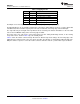
Table 2. H-Bridge Control Using Phase/Enable Mode
M1 xENBL xPHASE xOUT1 xOUT2
1 0 X Z Z
0 0 X 0 0
X 1 0 L H
X 1 1 H L
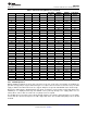
8.4.2 Indexer Mode
To allow a simple step and direction interface to control stepper motors, the DRV8834 contains a microstepping
indexer. The indexer controls the state of the H-bridges automatically. Whenever there is a rising edge at the
STEP input, the indexer moves to the next step, according to the direction set by the DIR pin.
The nENBL pin is used to disable the output stage in indexer mode. When nENBL = 1, the indexer inputs are still
active and will respond to the STEP and DIR input pins; only the output stage is disabled.
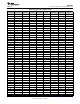
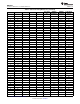
The indexer logic in the DRV8834 allows a number of different stepping configurations. The M0 and M1 pins are
used to configure the stepping format as shown in Table 3.
Copyright © 2012–2015, Texas Instruments Incorporated Submit Documentation Feedback 15
Product Folder Links: DRV8834