
Data Sheet

xOUT1
xOUT2
1
2
3
Drive Current
Slow decay
Fast decay
xVM
1
2
3
Full-Scale I =
TRIP
xVREF
¾
5 R·
ISENSE
DRV8834
www.ti.com
SLVSB19D –FEBRUARY 2012–REVISED MARCH 2015
Feature Description (continued)
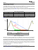
The blanking time also sets the minimum PWM duty cycle. This can cause current control errors near the zero
current level when microstepping. To help eliminate this error, the DRV8834 has a dynamic t
BLANK
time. When
the commanded current is low, the blanking period is reduced, which in turn lowers the minimum duty cycle. This
provides a smoother current transition across the zero crossing region of the current waveform. The end result is
smoother and quieter motor operation.
The PWM chopping current is set by a comparator which compares the voltage across a current sense resistor
connected to the xISEN pins, with a reference voltage supplied to the AVREF and BVREF pins. In indexer mode,
the reference voltages are scaled by internal DACs to provide scaled currents used to perform microstepping.
The chopping current is calculated as follows:
(1)
Example: If xVREF is 2 V (as it would be if xVREF is connected directly to VREFO) and a 400-mΩ sense resistor
is used, the chopping current will be 2 V / 5 × 400 mΩ = 1 A.
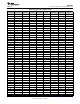
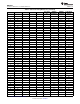
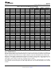
In indexer mode, this current value is scaled by between 5% and 100% by the internal DACs, as shown in the
step table in the "Microstepping Indexer" section of the data sheet.
If current control is not needed, the xISEN pins may be connected directly to ground. In this case, TI also
recommends connecting AVREF and BVREF directly to VREFO.
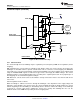
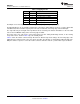
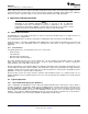
8.3.2 Current Recirculation and Decay Modes
During PWM current chopping, the H-bridge is enabled to drive current through the motor winding until the PWM
current chopping threshold is reached. This is shown in Figure 7 as case 1. The current flow direction shown
indicates positive current flow in the step table below for indexer mode, or the current flow with xPHASE = 1 in
phase/enable mode.
Once the chopping current threshold is reached, the drive current is interrupted, but due to the inductive nature
of the motor, the current must continue to flow. This is called recirculation current. To handle this recirculation
current, the H-bridge can operate in two different states, fast decay or slow decay.
In fast decay mode, once the PWM chopping current level has been reached, the H-bridge reverses state to
allow winding current to flow in through the opposing FETs. As the winding current approaches zero, the bridge
is disabled to prevent any reverse current flow. Fast decay mode is shown in Figure 7 as case 2.
In slow decay mode, winding current is recirculated by enabling both of the low-side FETs in the bridge. Slow
decay is shown as case 3 in Figure 7.
Figure 7. Decay Modes
Copyright © 2012–2015, Texas Instruments Incorporated Submit Documentation Feedback 13
Product Folder Links: DRV8834