
Data Sheet

xOUT1
xOUT2
VM
xISEN
From Logic
Pre-
drive
VCP, VM
VM
PWM
OCP
OCP
Optional
Step
Motor
DAC
+
-
Comparator
CONFIG
xVREF
*5
5
From Indexer
DRV8834
SLVSB19D –FEBRUARY 2012–REVISED MARCH 2015
www.ti.com
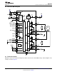
Feature Description (continued)
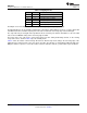
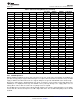
Figure 6. Motor Control Circuitry
8.3.1 Current Control
The current through the motor windings may be regulated by a fixed-frequency PWM current regulation (current
chopping).
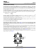
With stepping motors, current control is normally used at all times. Often it is used to vary the current in the two
windings in a sinusoidal fashion to provide smooth motion. This is referred to as microstepping. The DRV8834
can provide up to 1/32 step microstepping, using internal 5-bit DACs. Finer microstepping can be implemented
using the xPHASE/xENBL signals to control the stepper motor, and varying the xVREF voltages. The current
flowing through the corresponding H-bridge varies according to the equation given below. A very high degree of
microstepping can be achieved through this technique.
With DC motors, current control can be used to limit the start-up current of the motor to less than the stall current
of the motor.
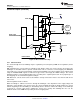
Current regulation works as follows:
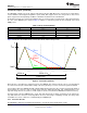
When an H-bridge is enabled, current rises through the winding at a rate dependent on the supply voltage and
inductance of the winding. If the current reaches the current chopping threshold, the bridge disables the current
until the beginning of the next PWM cycle. Immediately after the current is enabled, the voltage on the xISEN pin
is ignored for a period of time before enabling the current sense circuitry. This blanking time also sets the
minimum on time of the PWM when operating in current chopping mode.
12 Submit Documentation Feedback Copyright © 2012–2015, Texas Instruments Incorporated
Product Folder Links: DRV8834