
Data Sheet

Over-
Temp
AOUT1
GND
STEP / BENBL
VM
Logic
AOUT2
VM
Gate
Drive
&
OCP
BOUT1
VM
BOUT2
VM
Gate
Drive
&
OCP
BISEN
AISEN
Step
Motor
ISEN
ISEN
DIR / BPHASE
M0 / APHASE
M1
0.01µF
VM
VM
VCP
VM
Internal
Ref &
Regs
VINT
nFAULT
nSLEEP
AVREF
BVREF
VREFO
ADECAY
nENBL / AENBL
BDECAY
CONFIG
VM
VREFO
Charge
Pump
10µF
+
2.2µF
0.01µF
VM
VINT,
refs,
Int. supp.
VCP
PUC,
UVLO
VREFO
DCM
DCM
DRV8834
www.ti.com
SLVSB19D –FEBRUARY 2012–REVISED MARCH 2015
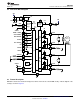
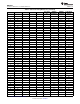
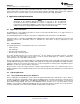
8.2 Functional Block Diagram
8.3 Feature Description
DRV8834 contains two identical H-bridge motor drivers with current-control PWM circuitry. A block diagram of the
circuitry is shown in Figure 6:
Copyright © 2012–2015, Texas Instruments Incorporated Submit Documentation Feedback 11
Product Folder Links: DRV8834