
Data Sheet

TB67S279FTG
2017-09-15
15
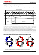
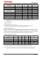
14. ADMD + ACDS (sense-resistor less PWM) control
ADMD (Advanced Dynamic Mixed Decay)
The TB67S279FTG applied the ADMD architecture which monitors both charge and recirculating current during constant
current PWM. The basic sequence of the ADMD is as shown below.
Timing charts may be simplified for explanatory purpose.
The basic constant current PWM sequence is a loop of Charge→Fast Decay→Slow Decay→Charge→・・・ to keep the peak
current below the threshold. The chopping frequency (fchop) is a period of 16 counts per cycle of OSCM oscillator
frequency (fOSCM). The sequence of Charge, Fast Decay, and Slow Decay is switched within this fchop cycle.
First, the motor current is charged (Charge sequence) until it reaches the constant current threshold (NFth), which is set by
the VREF reference voltage. Once the motor current reaches the constant current threshold (NFth), a partial motor current
recirculates back to the power supply (Fast Decay sequence). When the motor current reaches the fixed value (ADMDth)
during recirculation; for the rest of the fchop cycle, the motor is controlled to naturally discharge and hold the motor current
as much as possible (Slow Decay sequence).
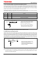
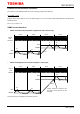
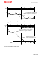
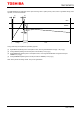
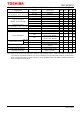
Motor output MOSFET operation mode (Advanced Dynamic Mixed Decay)
Note: Fixed value of 400 ns (design value) is prepared at the switching timing of MOSFET output to avoid any flow-through
current. The equivalent circuit diagrams may be simplified or omitted for explanatory purposes.
Charge
Fast Decay
Slow Decay
Mixed (Fast+Slow) Decay
fOSCM
fchop (=1/16 fOSCM)
NFth
ADMDth
IOUT
VM
RSAGND/
RSBGND
OUTA+/
OUTB+
OUTA-/
OUTB-
VM
RSAGND/
RSBGND
OUTA+/
OUTB+
OUTA-/
OUTB-
VM
RSAGND/
RSBGND
OUTA+/
OUTB+
OUTA-/
OUTB-
Charge
Fast Decay
Slow Decay