
Data Sheet

TB67S279FTG
2017-09-15
11
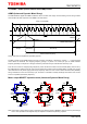
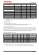
7. LO1, LO2 (Error Output: error detect flag output) function
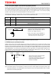
The LO1 and LO2 are signals that are flagged when the error state is detected. Both pins are open drain type, therefore to
use the function properly; the LO1 and LO2 pins should be pulled up to the VCC. (Set the pull-up resistor in the range of
10k to 100kΩ.) During normal operation, the pin is high-impedance (Internal MOSFET is turned off and the pin voltage is
VCC). Once the error detect function (thermal shutdown (TSD), over current detection (ISD), or motor load open (OPD))
operates, the pins will output Low level (Internal MOSFET is turned ON) as follows.
Reasserting the VM power or using the standby mode to release the error detection status, the LO1 and LO2 pins will show
“normal operation” status again. If function of LO1 or LO2 is not used, leave the pins open.
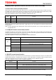
LO1 LO2 Function
VCC (Hi-Z) VCC (Hi-Z)
Normal status (Normal operation)
VCC (Hi-Z) Low
Detected motor load open (OPD)
Low VCC (Hi-Z)
Detected over current (ISD)
Low Low
Detected over thermal (TSD)
Note: Hi-Z: High impedance state
Note: The equivalent circuit diagrams may be simplified or omitted for explanatory purposes.
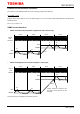
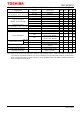
8. OSCM (internal oscillator) function
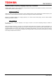
OSCM is used to set the internal oscillator frequency for constant current PWM control. The values of the resistor and the
capacitor connected to this pin will set the OSCM frequency. Please connect the pull-up resistor to the VCC when PWM
frequency is set by the external components. Also, to use an internal ‘fixed value OSCM frequency’ (not using any external
components), disconnect the ROSC resistor and short the OSCM pin to the GND. Note that when using the internal ‘fixed
value OSCM frequency’, do not input any control signal for 20 μs (typ.) after power on or standby release. (It takes 20 μs to
judge the existence of the external components and switch to the ‘fixed value OSCM frequency’ mode.) The ‘fixed value
OSCM frequency’ will be around 0.92 MHz, so the fchop will be around 57 kHz.
Note: The equivalent circuit diagrams may be simplified or omitted for explanatory purposes.
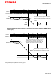
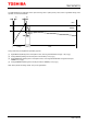
Note: The oscillator frequency can be adjusted by controlling the values of resistor (ROSC) and capacitor (COSC). When
conforming the frequency, it is recommended to fix the capacitor to 270 pF and change the ROSC value. For details,
please refer to the following descriptions.
(10 kΩ to 100 kΩ)
LO1, LO2
VCC
Once the error detection operates, internal
MOSFETs of both or either LO1 or LO2 is
turned on. (Pin voltage is low level.)
During normal state, internal MOSFETs of
both LO1 and LO2 are OFF. (The pin will
output High level (pull-up voltage of VCC).
(ROSC)
OSCM
VCC
When using the internal ‘fixed value OSCM
frequency’ (not using any external
components), disconnect the ROSC resistor
and short the COSC capacitor (short the
OSCM pin to the GND).
(COSC)