
Data Sheet

TB67S249FTG
2017-08-18
13
♦Stepping motor application features (anti-stall, sense resistor less PWM)
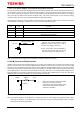
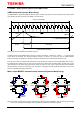
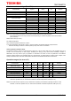
9. Active Gain Control (Anti-stall) function
AGC0, AGC1 pins control the Active Gain Control to turn on or off. When both pins are set to High, the AGC is turned on.
The PWM current threshold will be reduced in a phased manner where the upper limited current is determined by VREF.
When both pins are set to Low, the AGC is turned off and the current, which is set by VREF, flows.
Note: Built-in digital filter of 0.625 μs (±20%) is adopted to AGC0 and AGC1 pins.
AGC0 AGC1 Function
High High
AGC: ON
High Low
(Note1)
Low Low
AGC: OFF
Normally, set these pins as follows; AGC0, AGC1= (High, High) or (Low, Low). Please do not switch the AGC0 pin level
during operation.
Note1: Use this configuration when switching ON or OFF of AGC during operation. As for concrete usage method, refer to
the application note.
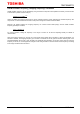
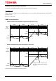
10. CLIM (AGC bottom current limit) function
The CLIM0 and CLIM1 pins set the bottom current limit of the AGC. When AGC is active, the PWM current threshold will be
reduced in a phased manner. By using the CLIM function, the motor current will not go below the bottom limit. The CLIM0 is
a 2 stated logic input, and the CLIM1 is a 4 stated logic input.
Note: Built-in digital filter of 0.625 μs (±20%) is adopted to CLIM0 and CLIM1 pins.
CLIM0 CLIM1 Function
High
VCC short
AGC bottom current limit: IOUT x 80 %
VCC-100 kΩ pull-up
AGC bottom current limit: IOUT x 75 %
GND-100 kΩ pull-down
AGC bottom current limit: IOUT x 70 %
GND short
AGC bottom current limit: IOUT x 65 %
Low
VCC short
AGC bottom current limit: IOUT x 60 %
VCC-100 kΩ pull-up
AGC bottom current limit: IOUT x 55 %
GND-100 kΩ pull-down
AGC bottom current limit: IOUT x 50 %
GND short
AGC bottom current limit: IOUT x 45 %
Note: Resistance accuracy should be within ±20 %.
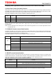
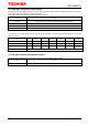
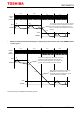
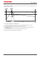
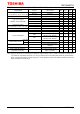
11. BOOST (current boost) function
The BOOST pin sets the current boost level when the load torque is increased. When AGC is turned on, the PWM current
threshold will be reduced in a phased manner. However, once the load torque is increased, the device will then boost the
PWM current threshold to prevent the motor from stalling. The BOOST pin is a 4 stated logic input pin.
Note: Built-in digital filter of 0.625 μs (±20%) is adopted to BOOST pin.
BOOST Function
VCC short
Takes 5 steps maximum to reach 100 % current (design value)
VCC-100 kΩ pull-up
Takes 7 steps maximum to reach 100 % current (design value)
GND-100 kΩ pull-down
Takes 9 steps maximum to reach 100 % current (design value)
GND short
Takes 11 steps maximum to reach 100 % current (design value)
Note: Resistance accuracy should be within ±20 %.
Note: Current boost step is largest when BOOST is shorted to VCC, and smallest when shorted to the GND.