
Data Sheet

TB67S279FTG, TB67S289FTG, TB67S249FTG Application Note
2018-03-07
9 / 33
Preliminary
8. Function Explanation
This chapter describes the basic functions of stepping motors.
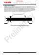
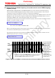
8.1. CLK function
An electrical angle advances one unit according to the driving mode, which is configured by each
pulse of CLK signal. Each signal is reflected at upper edge of CLK signal.
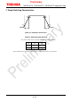
The analog filter of 200 ns (±20%) is implemented for CLK pin to avoid malfunction due to noise.
Duty of CLK signal is not necessary to set 50 %. However, pay attention to configure the maximum
frequency of the CLK signal in considering this analog filter of 200 ns.
When the state of inputting upper edge signal continues due to noise, upper edge signal is reflected
after the filtering period. In this case, the motor may stall because the electrical angle advances
according to the below function regardless of the signal reflecting state. Pay attention to design the
wiring layout for CLK pin not to be influenced by noise.
CLK Function
Upper edge Shifts the electrical angle and current step per each upper edge.
Down edge — (no change, maintain former state)
8.2. ENABLE function
This function switches ON and OFF of the output circuit of the IC. Motor operation (i.e., current
outputting) starts when this function is enabled. Motor operation stops when it is disabled. (In
OFF mode, all of output MOSFETs are turned off and become the high impedance state.) To
prevent the motor from operating outside the VM operating voltage range, following ENABLE pin
setting is recommended. Configure ENABLE pin to low level in powering on and shutdown, and
switch it to high level after VM voltage is stabilized at the usage voltage.
ENABLE Function
High Motor operation: ON (Normal operation)
Low Motor operation: OFF (Hi-Z)
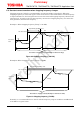
8.3. CW/CCW function (Output logic at charge start)
This function controls the rotation direction of the stepping motor. When CW/CCW pin is set to
high level, OUT (+) pin outputs a high level signal and OUT (-) pin outputs a low level signal in the
charge starting. When CW/CCW pin is set to low level, OUT (+) pin outputs a low level signal and
OUT (-) pin outputs a high level signal in the charge starting.
CW/CCW Function
High Clock-wise: The current of Ach leads the current of Bch by 90-degree phase difference.
Low Counter clock-wise: The current of Bch leads the current of Ach by 90-degree phase difference.