
Data Sheet

TB67S279FTG, TB67S289FTG, TB67S249FTG Application Note
2018-03-07
5 / 33
Preliminary
6.2. Setting internal oscillation frequency (f
OSCM
) and constant current PWM (chopping)
frequency (fchop)
TB67S279FTG, TB67S289FTG, and TB67S249FTG can set the internal oscillation frequency
(f
OSCM
) and the PWM (chopping) frequency (fchop) with the constant numbers of the external
components (resistor and capacitor), which are connected to OSCM pin.
The internal oscillation frequency can be set by connecting the resistor (ROSC) between VCC and
OSCM pin, and connecting the capacitor (COSC) between OSCM pin and GND. Please set it by
changing the ROSC value, while fixing the COSC value to 270 pF.
The relational expression of the internal oscillation frequency (f
OSCM
) and the external resistance
(ROSC) is as follows (COSC = 270 pF);
f
OSCM
= 4.0 × ROSC
-0.8
Note: Unit: f
OSCM (
MHz) and ROSC (kΩ)
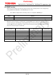
Refer to the following graph for the relation of the external component and the measured data of
the internal oscillation frequency (reference data).
The relational expression of the internal oscillation frequency (f
OSCM
) and the constant current
PWM (chopping) frequency (fchop) is as follows;
fchop = f
OSCM
/ 16
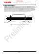
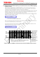
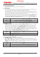
Figure 6.1 Relation of OSCM pin oscillation waveform and internal OSCM oscillation waveform
OSCM
oscillation
waveform
(It can be monitored by
OSCM
pin. Waveform
inclination
changes
depending on the
external
component.)
Internal
OSCM
oscillation
waveform
(OSCM oscillation
frequency waveform is
fabricated
to the
r
ectangle waveform by
comparing to the
reference data. It
cannot
be monitored
by
external
devices.)
Operation is controlled with constant current by applying 16 counts of
the internal OSCM oscilla
tion waveform as one cycle.