
Data Sheet

TB67S279FTG, TB67S289FTG, TB67S249FTG Application Note
2018-03-07
31 / 33
Preliminary
Notes on Contents
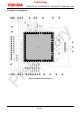
1. Block Diagrams
Some of the functional blocks, circuits, or constants in the block diagram may be omitted or simplified
for explanatory purposes.
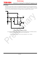
2. Equivalent Circuits
The equivalent circuit diagrams may be simplified or some parts of them may be omitted for
explanatory purposes.
3. Timing Charts
Timing charts may be simplified for explanatory purposes.
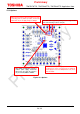
4. Application Circuits
The application circuits shown in this document are provided for reference purposes only. Thorough
evaluation is required, especially at the mass production design stage.
Any license to any industrial property rights is not granted by provision of these application circuit
examples.
5. Test Circuits
Components in the test circuits are used only to obtain and confirm the device characteristics. These
components and circuits are not guaranteed to prevent malfunction or failure from occurring in the
application equipment.
IC Usage Considerations
Notes on handling of ICs
(1) The absolute maximum ratings of a semiconductor device are a set of ratings that must not be
exceeded, even for a moment. Do not exceed any of these ratings.
Exceeding the rating(s) may cause the device breakdown, damage or deterioration, and may result
injury by explosion or combustion.
(2) Use an appropriate power supply fuse to ensure that a large current does not continuously flow in
the case of over current and/or IC failure. The IC will fully break down when used under conditions
that exceed its absolute maximum ratings, when the wiring is routed improperly or when an
abnormal pulse noise occurs from the wiring or load, causing a large current to continuously flow
and the breakdown can lead to smoke or ignition. To minimize the effects of the flow of a large
current in the case of breakdown, appropriate settings, such as fuse capacity, fusing time and
insertion circuit location, are required.
(3) If your design includes an inductive load such as a motor coil, incorporate a protection circuit into the
design to prevent device malfunction or breakdown caused by the current resulting from the inrush
current at power ON or the negative current resulting from the back electromotive force at power
OFF. IC breakdown may cause injury, smoke or ignition.
Use a stable power supply with ICs with built-in protection functions. If the power supply is
unstable, the protection function may not operate, causing IC breakdown. IC breakdown may cause
injury, smoke or ignition.
(4) Do not insert devices in the wrong orientation or incorrectly.
Make sure that the positive and negative pins of power supplies are connected properly.
Otherwise, the current or power consumption may exceed the absolute maximum rating, and
exceeding the rating(s) may cause the device breakdown, damage or deterioration, and may result
in injury by explosion or combustion.
In addition, do not use any device inserted in the wrong orientation or incorrectly to which current
is applied even just once.