
Data Sheet

TB67S279FTG, TB67S289FTG, TB67S249FTG Application Note
2018-03-07
30 / 33
Preliminary
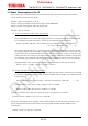
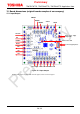
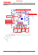
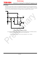
15.5. SVF pin
The motor current and the torque can be changed during operation by using our optional pattern
on the board. (Please refer to below circuit diagram.) The applied voltage for VREF can be adjusted
by switching the voltage-dividing ratio with the transistor. Use an appropriate resistor for the SVF
input (i.e., the base of the transistor) in accordance with the capability of the transistor.
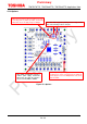
Figure 15.5 Circuit diagram of SVF pin
Note: Total value of the resistance, which is connected between VCC and GND, should be
10 kΩ to 50 kΩ regardless of the transistor’s switching state.
TVF recommended resistor: NPN transistor RN1401 of our company
VCC
RVF1
VREFB
RVF2
RVF3
SVF
TVF
VREFB
VREFA
CVF
VREFA
SR5