
Data Sheet

TB67S279FTG, TB67S289FTG, TB67S249FTG Application Note
2018-03-07
24 / 33
Preliminary
13. Power dissipation
Relation equation of the ambient temperature (T
a
), the junction temperature (T
j
), and the heat
resistance (R
th(j-a)
) between the junction temperature and the ambient temperature is as follows;
T
j
= T
a
+ P × R
th(j-a)
The IC adopts a surface mounting package, QFN48. QFN48 package radiates the heat mainly from
the heat sink of the IC back side to the mounting board. So, R
th(j-a)
depends on the board design
pattern, GND area, etc.
Electrode part (corner pad) for disabled pins of QFN package is connected to the heat sink in the IC.
Connect this part to the board by soldering because heat can be radiated from the board surface.
Example of thermal calculation: If R
th(j-a)
is 25 °C/W when the IC is mounted on glass-epoxy 4-layer
board, the junction temperature at ambient temperature (Ta
= 25 °C) can be calculated from below
formula. Conditions of the power consumption are as the same as the prior section ‘Power
Consumption of the IC’.
T
j
= 25 (°C) + 0.964 (W) × 25 (°C/W) = 49.1 °C
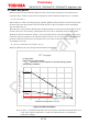
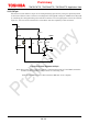
Reference) Relation of power dissipation and ambient temperature
Figure 10.1 Power dissipation
Note: T
a
, R
th(j-a)
, and P(total) depend on the environment, in which the board and motor are
used. If the ambient temperature is high, the allowable power consumption is
reduced accordingly.
0
1
2
3
4
5
6
0 25 50 75 100 125 150
Power dissapation PD (W)
Ambient temperature Ta (°C)
PD -Ta graph
(1) Stand alone
(2) Mounting on 4-layer board
R
th(j-a)
= 25°C/W, This value depends on the board design pattern
and mounting conditions.
Topr
(2)
(1)