
Data Sheet

TB67S279FTG, TB67S289FTG, TB67S249FTG Application Note
2018-03-07
21 / 33
Preliminary
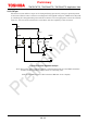
11.3. Resistor for monitor pin
The IC has MO, LO1, and LO2 open-drain type pins to output some of the internal status of the IC.
When internal open-drain MOSFETs turn off, these pins show high impedance. In using this
function, they should be pulled up to the power supply (3.3 V/5 V) such as VCC. If this function is
not used, leave the pins open or connect them to GND.
Table 11.3 Recommended resistor values for monitor pins
Item Components Typ. Recommended range
Between (MO/LO1/LO2 pin) and
power supply
Chip/Lead resistor 10 kΩ 10 kΩ to 100 kΩ
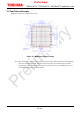
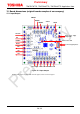
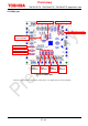
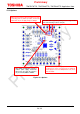
11.4. Wiring pattern for power supply and GND
Since large current is assumed to flow in the pattern connected to VM, OUT, and GND pins in
particular, design the appropriate board in order to avoid the influence of wiring impedance. It is
very important for surface mounting packages such as QFN type to radiate the heat from the IC
back side (the corner pad and the heat sink) to the GND (i.e., heat sink mounting area). So, design
the pattern by considering the heat design.
11.5. Fuse
Use an appropriate power supply fuse for the power supply line to ensure that a large current does
not continuously flow in the case of over current and/or IC failure.
The IC will fully break down when used under conditions that exceed its absolute maximum
ratings, when the wiring is routed improperly or when an abnormal pulse noise occurs from the
wiring or load, causing a large current to continuously flow and the breakdown can lead to smoke
or ignition. To minimize the effects of the flow of a large current in the case of breakdown,
appropriate settings, such as fuse capacity, fusing time and insertion circuit location, are required.
This IC incorporates over current detection circuit (ISD) that turns off the output of the IC when
over current is detected in the IC. However, it does not necessarily protect ICs under all
circumstances. If the over current detection circuits operate against the over current, clear the
over current status immediately. Depending on the method of use and usage conditions, such as
exceeding absolute maximum ratings can cause the over current protection circuit to not operate
properly or IC breakdown before operation. In addition, depending on the method of use and usage
conditions, if over current continues to flow for a long time after operation, the IC may generate
heat resulting in breakdown.
To avoid above IC destruction and malfunctions caused by noise, the over current detection circuit
has a dead band time. So, it is concerned that the over current detection circuit may not operate
depending on the output load conditions because of the dead band time. Therefore, in order to
avoid continuing this over current state, use the fuse for the power supply line.