
Data Sheet

TB67S279FTG, TB67S289FTG, TB67S249FTG Application Note
2018-03-07
2 / 33
Preliminary
1. Outline of IC
TB67S279FTG, TB67S289FTG, and TB67S249FTG can control a single 2-phase bipolar stepping
motor.
This IC supports from 12 V to 42 V power supply and large-current drive for motors by adopting 50 V
monolithic analog process (BiCD: Bipolar CMOS DMOS).
The specification differences between TB67S279FTG, TB67S289FTG, and TB67S289FTG are output
capabilities (capabilities of Ron and Iout), Gain (VREF (gain)) that determines the constant current
rating, and over current detection (ISD) threshold. Pin assignments are same.
CLK-In Decoder for micro stepping drive is incorporated, allowing motors to drive with sine-wave
current by inputting CLK signals. It realizes fast and accurate current following with ADMD
(Advanced Mixed Decay Mode).
Also, external components can be eliminated by adopting ACDS (Advanced Current Detection
System) and the component-elimination mode of the internal oscillation circuit. The greatest feature
of the IC is adopting AGC (Active Gain Control: anti-stall function) technology. It can achieve high
efficient motor drive, while preventing motor stalls.
Usage methods and notes in using the IC are described from the next section.
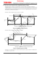
2. Power Supply Voltage
2.1. Power supply voltage and operation range
In using TB67S279FTG, TB67S289FTG, and TB67S249FTG, the voltage should be applied to the
pins of VM (VMA, VMB) and VREF (VREFA, VREFB).
Built-in VCC regulator for internal logic power supply enables the IC to operate with a single
power supply. Applying an external voltage is unnecessary. The maximum rating of the motor
supply voltage is 50 V. Its operation voltage range is 10 V to 47 V.
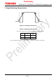
The maximum voltage rating, which is applied to VREF pin for PWM threshold, is 5 V. Its
operation range is 0 to 3.6 V.
VREF is configured by voltage of VCC regulator and can be set by dividing voltage in necessary.
However, if the current value exceeds the capability of the VCC regulator, the output voltage may
not be kept.
Therefore, when VREF is applied by dividing VCC, the voltage-dividing resistance (combined
resistance of VCC and GND) should be in the range of 10 kΩ to 100 kΩ.
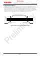
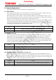
Table 2.1 Operation ranges of power supply voltage (Ta=-20 to 85°C)
Item Symbol
Absolute
maximum ratings
Operation range Unit Remarks
Motor power supply voltage VM 50 10 to 47 V —
Setting voltage for PWM threshold
VREF 5.0 0 to 3.6 V —
Voltage for internal logic power
supply
VCC 6.0 4.75 to 5.25 V
Supplied by internal
regulator