
Data Sheet

TB67S279FTG, TB67S289FTG, TB67S249FTG Application Note
2018-03-07
18 / 33
Preliminary
11. External Component Description
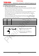
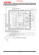
11.1. Capacitors for power supply pins
To stabilize the power supply voltage of the IC and reduce the noise, connect an appropriate
capacitor to each pin.
It is effective and recommended to connect capacitors as close to the IC as possible.
However, be sure to consider the influence of the IC’s heat generation.
Also, connecting the small-capacity ceramic capacitor (bypass capacitor) near the IC is effective to
reduce power supply fluctuations and noise especially at the high frequency range. Generally, this
can be adopted to dealing of CMOS LOGIC IC board.
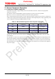
Table 11.1 Recommended capacitor values for power supply pins
Item Components Typ. Recommended range
Between VM pin and
GND
Decoupling capacitor
(CVM1)
100 μF 22 to 100 μF
Between VCC pin and
GND
Bypass capacitor (CVCC) 0.1 μF 0.01 to 1 μF
Between VREF pin and
GND
Bypass capacitor (CVF) 0.1 μF 0.01 to 1 μF
Connect the capacitor in necessary between VREF pin and GND in accordance with the usage
environment.
It is possible to remove the capacitor and use other than the recommended one depending on the
motor load condition and the designed pattern of the board. For example, in case of using two or
more motors (the same number of driver ICs as the motors are used), the capacitor between VM
pin and GND can be reduced. Comprehensively, ensure the capacitor not to increase the ripple of
the power supply.