
Data Sheet

TB67S279FTG, TB67S289FTG, TB67S249FTG Application Note
2018-03-07
16 / 33
Preliminary
9. IC Signal Output Function
9.1. LO1, LO2 (Error Output: Error detect flag output) function
LO1 pin and LO2 pin output signals when the error state of the IC or its environment is detected.
Both pins are open drain type like MO pin, therefore to use the function properly, they should be
pulled up to the power supply (3.3 V/5 V) such as VCC.
Use the pull-up resistor in the range of 10 kΩ to 100 kΩ.
During normal operation, they are high-impedance (Internal open-drain MOSFETs turn off and
pin voltage is VCC). Once the error detect function (thermal shutdown (TSD), over current
protection (ISD), or motor load open (OPD)) operates, pin voltage becomes low level (Internal
open-drain MOSFETs turn ON).
When the error detection is released by reasserting the VM power supply or using the standby
mode, LO1 pin and LO2 pin show “normal operation” status again. If this function is not used,
leave the pins open or connect them to GND.
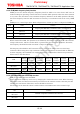
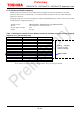
LO1 LO2 Function
High (Hi-Z) High (Hi-Z)
Normal state (Normal operation)
High (Hi-Z) Low
Detects motor load open (OPD)
Low High (Hi-Z)
Detects over current (ISD)
Low Low
Detects over thermal (TSD)
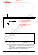
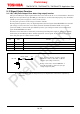
Note: The equivalent circuit diagrams may be simplified or omitted for explanatory
purposes.
10 kΩ to 100 kΩ
LO1, LO2
VCC
Once the error detection operates, internal
MOSFETs of both or either LO1 or LO2 are
turned on. (Pin voltage is low level.)
During normal state, internal MOSFETs of
both LO1 and LO2 are turned off. (The pin
voltage is high level (VCC).