
Data Sheet

TB67S279FTG, TB67S289FTG, TB67S249FTG Application Note
2018-03-07
14 / 33
Preliminary
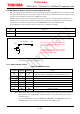
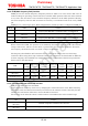
8.6.3. BOOST (current boost) function
BOOST pin sets the current boost level (i.e., return to the initial constant current setting value)
when the load torque increases. BOOST pin is a 4 stated logic input pin, setting the compensation
value in accordance with the existence of the 100 kΩ-resistor.
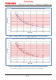
In the following table, Mode 1 has the fastest current recovery, and Mode 4 has the slowest one.
The "step" of the function in the table means the number of divisions of the current change,
indicating that the smaller this value is, the faster the current boosts (i.e., recovers).
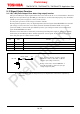
Determination of the mode depends on the load torque change of the used system. For example, in
using the system with rapid torque fluctuations, Mode 1 is suitable. In using the system with slow
torque fluctuations, Mode 3 or Mode 4 can be adopted. In general, it is recommended to evaluate
the operation by using Mode 1 as the standard and shift to Mode 2 and Mode 3 to verify whether
the torque-following is possible or not.
Built-in digital filter of 0.625 μs (±20%) is adopted to BOOST pin.
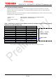
Mode BOOST Function Recovery speed
1 Connected to VCC
Takes 5 steps in maximum to reach
100 % current (design value)
Fast
2
Pulled up to VCC with100
kΩ-resistor
Takes 7 steps in maximum to reach
100 % current (design value)
Slightly fast
3
Pulled down to GND
with100 kΩ-resistor
Takes 9 steps in maximum to reach
100 % current (design value)
Slightly slow
4 Connected to GND
Takes 11 steps in maximum to reach
100 % current (design value)
Slow