
Data Sheet

TB67S279FTG, TB67S289FTG, TB67S249FTG Application Note
2018-03-07
12 / 33
Preliminary
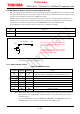
8.6. AGC (Active Gain Control)
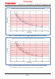
AGC is an abbreviation for Active Gain Control that is our original driving technology. When
required motor torque is lower than the configured constant current value, the motor can drive
efficiently by decreasing driving current. When higher torque is required, motor stall can be
prevented by increasing the constant current value.
8.6.1. AGC0 and AGC1 functions
AGC0 pin and AGC1 pin switch ON/OFF of the Active Gain Control (AGC).
When both pins are set to high level, AGC turns on. The motor current is decreased according to
the load torque. Upper current limit is determined by VREF.
When pin configuration is (AGC0, AGC1) = (Low, Don’t Care), AGC is turned off. The IC can be
used as a constant current driver because it operates with the current, which is set by VREF.
The difference between the configurations of (AGC0, AGC1) = (Low, Don’t Care) and (AGC0,
AGC1) = (High, Low) is waveforms in full step resolution.
AGC monitors the state of each output pin where the current value continues to be zero, and use
this monitoring result for internal signal detection. However, in full step resolution drive,
continuous period of zero-level current does not exist in principle. Therefore, the IC generates the
judging period by controlling a certain period of zero-level current. This period is automatically
generated by the IC, so users do not need to control the period externally.
In the case of switching AGC (e.g., fixing AGC0 pin high level and switching AGC1 pin from high
to low level.) (Note), zero-level current duration is always provided also in the full step resolution.
This reduces the change of current waveforms occurred by turning on or off AGC.
On the other hand, in the case that AGC0 pin is set to low level and AGC1 pin is set ‘Don’t care’,
this zero-level current duration is not configured because it is not necessary. In this mode, the IC
can be used as a general CLK-In type driver.
Built-in digital filter of 0.625 μs (±20%) is adopted to AGC0 and AGC1 pins.
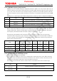
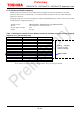
AGC0 AGC1 Mode Function
Existence of zero-level
current period in full step
resolution
High High
AGC ON mode Anti-stall function (AGC): ON Exist
High Low
AGC Active OFF mode Anti-stall function (AGC): OFF Exist
Low
(Don’t
care)
AGC OFF mode Anti-stall function (AGC): OFF No exist
Note: Generally, when using this IC, fix the pin configuration in either (AGC0, AGC1) =
(High, High) (i.e., AGC ON mode) or (AGC0, AGC1) = (Low, Don't care) (i.e., AGC
OFF mode).
When it is necessary to switch the anti-stall function (AGC) on or off during motor
driving, use the ‘AGC Active OFF mode’ by switching the AGC1 pin level.
Do not switch the AGC0 pin level during motor operation.