
Data Sheet

TB67S279FTG, TB67S289FTG, TB67S249FTG Application Note
2018-03-07
11 / 33
Preliminary
8.5. MO (Monitor Output: electrical angle output) function
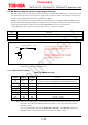
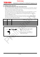
MO pin outputs an internal initial electrical angle as a signal. Since MO pin is an open drain type
pin, please pull up this pin to the power supply such as VCC to enable this function. (The pull-up
resistor value should be set between 10 kΩ and 100 kΩ.)
MO pin outputs high level with the pulled-up state because it is in high impedance (Hi-Z) state
during the normal operation. When the internal electrical angle corresponds to the initial angle,
the pin level becomes low (internal open-drain MOSFET turns on) as shown below.
In case MO pin is not used, leave the pin open state or connect it to GND.
MO Function
High (Hi-Z)
Electrical angle is not at the initial position
Low
Electrical angle is at the initial position
Note: The equivalent circuit diagrams may be simplified or some parts of them may be
omitted for explanatory purposes.
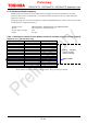
8.5.1. Step resolution setting
Table 8.1 DMODE function
DMODE0 DMODE1 DMODE2 Function
Low Low Low
Standby mode
(Internal oscillator circuit (OSCM) and output MOSFETs turn off.)
Low Low High Full step resolution
Low High Low Half (a) step resolution
Low High High Quarter step resolution
High Low Low Half (b) step resolution
High Low High 1/8 step resolution
High High Low 1/16 step resolution
High High High 1/32 step resolution
Note: After the standby mode is released, do not input a motor driving signal until the
internal circuit becomes stable. (Indication time is 1 ms after the release of the
standby mode.)
It is recommended to switch the DMODE0, DMODE 1, and DMODE 2 after the
RESET signal is set to low level in the initial state (MO = Low).
10 kΩ to 100 kΩ
MO
VCC
If the electrical angle corresponds to the initial
angle, the internal MOSFET turns on and the
pin voltage level is low.
If the electrical angle is not equal to the initial
angle, the internal MOSFET turns off and the
pin voltage level is high (VCC).