
Data Sheet

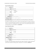


SCL pin configuration
Offset 0x3B
Type 8-bit
Data
• Bits 0–3: Pin function:
◦ 0: Default (see below)
◦ 1: User I/O
◦ 2: User input
◦ 3: Potentiometer power (drives high)
◦ 4: SCL (I²C clock line)
◦ 7: Kill switch
• Bits 4–5: reserved, should be 0
• Bit 6: Enable analog readings
• Bit 7: Enable internal pull-up
Default 0
Settings
file
scl_config
Settings
file data
Space-separated list including a subset of pin options ( pullup , analog , and
active_high ) and one pin function: default , user_io , user_input , pot_power ,
serial (SCL), or kill_switch .
Tic
Control
Center
Advanced settings tab, Pin configuration box, SCL
This byte contains most of the configuration of the SCL pin, as described in Section 5.5.
If the pin function is set to “Default”, then the Tic will ignore all of the options set in this byte and just
use default settings. The default settings for SCL depend on the control mode: in an analog control
mode, SCL is configured as a potentiometer power pin, while in all other control modes, the SCL pin
is used as the I²C clock line with its internal pull-up enabled.
Note that the settings file has all of the SCL configuration options on one line, but in the Tic’s
EEPROM, those settings are stored in multiple places: the SCL pin configuration byte, the switch
polarity map byte, and the kill switch map byte.
Tic Stepper Motor Controller User’s Guide © 2001–2018 Pololu Corporation
6. Setting reference Page 97 of 150