
Data Sheet


Effect: Energize
During normal operation or while it is starting up, the Tic will energize the stepper motor coils by
enabling its stepper motor driver.
Effect: Obey input
During normal operation, the Tic sets the stepper motor’s “Target position” or “Target velocity” as
specified by its main input.
The motion specified by the main input is held in the “Input state” and “Input after scaling” variables.
In the “Serial / I²C / USB” control mode, those variables are set by the “Set target position”, “Set target
velocity”, “Halt and hold”, “Halt and set position”, and “Reset” commands, and they do not get reset
when an error happens. In other control modes, those variables are set automatically.
Effect: Learn position
When the control mode is “RC position”, “Analog position”, or “Encoder position”, and the Tic starts
normal operation, it will check the “Position uncertain” flag. If that flag is set, the Tic will assume that
the stepper motor has already reached the position specified by the main input, and so it will set its
“Current position” variable equal to the “Target position”, and clear the “Position uncertain” flag.
This means that when you power on your system, or recover from certain errors, the Tic will assume
that its position is already correct, and not start moving right away to reach a new position. This
feature is similar to the safe start feature described above for the other control modes, because it helps
prevent the motor from moving by surprise.
If the Tic’s “Soft error response” is set to “Decelerate to hold” (the default) or “Go to position”, then
the “Position uncertain” flag will not be set when the Tic has a soft error, and therefore the Tic will not
learn its position when the soft error is resolved, and this could cause unexpected motion. Setting the
Tic’s “Soft error response” to “De-energize” or “Halt and hold” makes unexpected motion less likely.
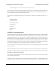
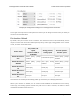
5.5. Pin configuration
This section explains how to configure the control pins of the Tic: SCL, SDA/AN, TX, RX, and RC.
The settings for these pins are found in the “Pin configuration” section of the “Advanced settings” tab
in the Tic Control Center, as shown below:
Tic Stepper Motor Controller User’s Guide © 2001–2018 Pololu Corporation
5. Details Page 75 of 150