
Data Sheet


after scaling” variable (which represents the target velocity being commanded by the Tic’s main input
source) is non-zero. This way, the Tic will never automatically start moving the motor just because
all the error conditions have been resolved; it will only start moving the motor if you first put its main
input in the neutral position (which maps to a speed of 0), and then move its main input away from
the neutral position. If an error happens while you are operating the motor, you will need to move your
main input back to the neutral position before you can start moving the motor again.
In the “Serial / I²C / USB” control mode, the Tic will generally set the “Safe start violation” error bit
whenever the Tic is not in the normal operation state. You can send an “Exit safe start” command to
clear the error for 200 milliseconds, giving the Tic a chance to start up. In general, you should only
send the “Exit safe start” command as a direct response to a user action, such as pressing a button.
That way, if an error happens and your motor stops, it will only start moving again in response to the
user’s action.
You can send the “Enter safe start” command to get back into safe start mode. This command forces
the “Safe start violation” bit to be set the next time the Tic evaluates it. After that, the “Safe start
violation” bit will only be cleared if the usual conditions for clearing it are satisfied, as described above.
In position control modes, where the safe-start feature generally has no effect, this command will
cause a temporary “Safe start violation” error that could interrupt movement of the motor.
You can check the “Disable safe start” checkbox in the “Advanced settings” tab of the Tic Control
Center to make the “Safe start violation” error never happen, even if an “Enter safe start” command is
sent.
The safe-start feature does not do anything useful in the “RC position”, “Analog position”,
or “Encoder position” control modes. In those modes, some safety can be provided by the
“Learn position” feature as described in the Effect: Learn position section below.
Condition: ERR line high
The Tic reports an “ERR line high” error if it is not driving its ERR pin high and the digital reading on
the ERR pin input is high. The error is cleared automatically when either of those conditions stops
being true. You can use the “Ignore ERR line high” setting to disable the error.
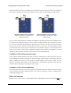
The Tic uses its ERR pin, which is connected to the red LED, to report errors. Whenever the Tic drives
the ERR line high to indicate an error, the red LED turns on. The red LED is in series with a 2.21kΩ
resistor. There is a 470Ω resistor with the ERR pin on one side, and the Tic’s microcontroller pin and
red LED on the other side.
When there is no error happening, the Tic’s ERR line acts as a digital input so it can detect error
Tic Stepper Motor Controller User’s Guide © 2001–2018 Pololu Corporation
5. Details Page 72 of 150