
Data Sheet
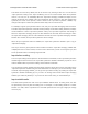
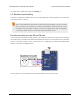
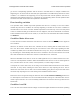

The Tic’s default encoder scaling
settings.
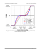
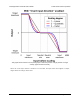
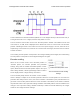
The time between the channel transitions (labeled T
1-4
in the diagram above) must be at least 100 µs.
The signal must rise to 4 V or higher, and must stay within 0 V to 5 V.
The Tic stores the raw encoder counts in the “Encoder position” variable. This variable can be read
over serial, I²C, or USB, and it is displayed in the “Status” tab of the Tic control center. The “Encoder
position” variable gets reset to zero when the Tic’s motor power supply is too low, when the Tic is
experiencing a motor driver error, when the Tic’s control mode is changed, and when the Tic receives
a Reset command.
An increasing encoder position corresponds to the TX signal leading the RX signal, and a decreasing
encoder position corresponds to the RX signal leading the TX signal.
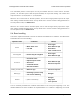
Encoder scaling
When the Tic’s control mode is set to “Encoder position” or
“Encoder speed”, the encoder prescaler and postscaler
settings, along with the “Enable unbounded position control”
option, determine how the encoder position maps to the “Input
after scaling” variable, a 32-bit signed integer which is used to
set the target position or target velocity of the motor.
The Tic internally keeps track of an encoder “cursor” variable,
which is always a multiple of the encoder prescaler. When the encoder position is more than the
prescaler value away from the cursor, the cursor increases or decreases by the prescaler amount to
get closer to the encoder position. When the cursor increases or decreases, the Tic adds or subtracts
the postscaler value to the “Input after scaling” variable if unbounded position control is enabled or the
change to the “Input after scaling” variable would keep it within the bounds defined by the “Target
maximum” and “Target minimum” settings.
Tic Stepper Motor Controller User’s Guide © 2001–2018 Pololu Corporation
5. Details Page 67 of 150